
Computer Hardware User Manual


Carrier Modulator Transmitter (CMT)
General Release Specification MC68HC05RC16 — Rev. 3.0
70 Carrier Modulator Transmitter (CMT) MOTOROLA
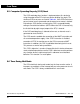
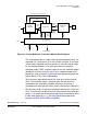
9.4 Carrier Generator
The carrier signal is generated by counting a predetermined number of
input clocks (500 ns for a 2-MHz oscillator) for both the carrier high time
and the carrier low time. The period is determined by the total number of
clocks counted. The duty cycle is determined by the ratio of high time
clocks to total clocks counted. The high and low time values are user
programmable and are held in two registers. An alternate set of high/low
count values is held in another set of registers to allow the generation of
dual frequency FSK (frequency shift keying) protocols without CPU
intervention. The MCGEN bit in the MCSR must be set and the BASE bit
in the MCSR must be cleared to enable carrier generator clocks. The
block diagram is shown in Figure 9-2.
Figure 9-2. Carrier Generator Block Diagram
CLK
6-BIT UP COUNTER
=?
=?
CLR
CLOCK AND OUTPUT CONTROL
PRIMARY HIGH COUNT REGISTER
SECONDARY HIGH COUNT REGISTER
COUNT REGISTER SELECT CONTROL
MODE
PRIMARY/
SELECT
CARRIER OUT
SECONDARY
BASE
f
OSC
MODULATOR/
CARRIER GENERATOR
ENABLE
PRIMARY LOW COUNT REGISTER
SECONDARY LOW COUNT REGISTER