
Computer Hardware User Manual


Carrier Modulator Transmitter (CMT)
Carrier Generator
MC68HC05RC16 — Rev. 3.0 General Release Specification
MOTOROLA Carrier Modulator Transmitter (CMT) 71
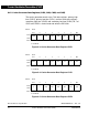
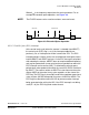
9.4.1 Time Counter
The high/low time counter is a 6-bit up counter. After each increment, the
contents of the counter are compared with the appropriate high or low
count value register. When this value is reached, the counter is reset and
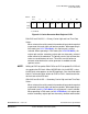
the compare is redirected to the other count value register. Assuming
that the high time count compare register is currently active, a valid
compare will cause the carrier output to be driven low. The counter will
continue to increment and when reaching the value stored in the
selected low count value register, it will be cleared and will cause the
carrier output to be driven high. The cycle repeats, automatically
generating a periodic signal which is directed to the modulator. The
lowest frequency (maximum period) and highest frequency (minimum
period) which can be generated are defined below.
f
min
= f
osc
÷ (2 x (2
6
– 1)) Hz
f
max
= f
osc
÷ (2 x 1) Hz
In the general case, the carrier generator output frequency is:
f
out
= f
osc
÷ (Highcount + Lowcount) Hz
Where:
0 <
Highcount
< 64 and
0 <
Lowcount
< 64
NOTE:
These equations assume the DIV2 bit (bit 6) of the MCSR is clear. When
the DIV2 bit is set, the carrier generator frequency will be half of what is
shown in these equations.
The duty cycle of the carrier signal is controlled by varying the ratio of
high time to low + high time. As the input clock period is fixed, the duty
cycle resolution will be proportional to the number of counts required to
generate the desired carrier period.
Duty Cycle
Highcount
Highcount Lowcount+
----------------------------------------------------------------=