
Laptop User Manual


Preparation
http://www.motorola.com/computer/literature 1-13
1
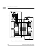
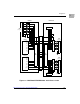
Serial Ports 1 and 2
On the TMCPN710, the asynchronous serial ports (Serial Ports 1 and 2)
are configured permanently as data circuit-terminating (Figure 1-4)
equipment (DTE). The COM1 port is also routed to a RJ-45 connector on
the front panel of the processor board. A terminal for COM1 may be
connected to either the processor board or the transition module, but not
both.
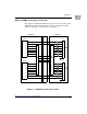
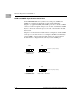
Jumper J7 on the transition module must be configured to enable COM1
on either the transition module or the processor board. To enable the
COM1 port on the transition module, connect pins 2-3 of J7. To enable
COM1 on the processor board, connect pins 1-2 of J7.
Note If the J7 jumper is not present on the TMCPN710, the board
automatically enables COM1 on the MCPN750A.
23
J7
123
J7
Serial Port 1 jumper settings
Enable COM1 on TMCPN710 Enable COM1 on MCPN750A
1
(factory configuration)