
Laptop User Manual


Hardware Installation
http://www.motorola.com/computer/literature 1-29
1
!
Warning
Dangerous voltages, capable of causing death, are present in
this equipment. Use extreme caution when handling, testing,
and adjusting.
!
Caution
Avoid touching areas of integrated circuitry; static discharge can damage
these circuits.
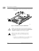
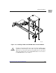
3. With the TMCPN710 or TM-PIMC-0001 in the correct vertical
position that matches the pin positioning of the corresponding
MCPN750A board carefully slide the transition module into the
appropriate slot and seat tightly into the backplane. Refer to Figure
1-11. TMCPN710 or TM-PIMC-0001/MCPN750A Mating
Configuration for the correct board/connector orientation.
4. Secure in place with the screws provided, making good contact with
the transverse mounting rails to minimize RF emissions.
5. Replace the chassis or system cover(s), making sure no cables are
pinched. Cable the peripherals to the panel connectors, reconnect
the system to the AC or DC power source, and turn the equipment
power on.