
User guide

20
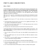
LCD_PORT
The LCD_PORT interface is connected to the MCU on the SPI port pins PS4/MISO,
PS5/MOSI, PS6/SCK, and PS7. The SPI serial signals are converted to parallel LCD control
and data signals by a serial to parallel shift register. Refer to the CMD912x board schematic
diagram for reference and MCU User Guide for SPI_0 register locations. Example software
to operate the LCD port with the SPI port is located on the support CD. See files
KLCD_SER.ASM, LCD_SER.ASM, and KEY12A.ASM.
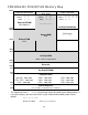
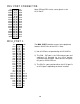
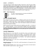
The interface supports all OPTREX DMC series displays in 4 bit bus mode with up to 80
characters and provides the most common pinout for a dual row rear mounted display
connector. Power, ground, and Vee are also available at this connector.
+5V 2 1 GND
RS 4 3 LCD-Vee
EN 6 5 GND (RW)
DB1 8 7 DB0
DB3 10 9 DB2
DB5 12 11 DB4
DB7 14 13 DB6
LCD-Vee is adjusted by the CONTRAST Potentiometer
(adjustable resistor).
RS = LCD register select, 0=Command, 1 = data
EN = LCD Enable, controls transfer of data.
DB0 - 3 are not applied for 8 bit interface.
DB4 - 7 are applied for the 4 bit interface.
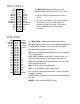
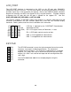
KEYPAD
1
PH0
2
PH1
3
PH2
4
PH3
5
PH4
6
PH5
7
PH6
8
PH7
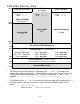
The KEYPAD connector is a passive 8-pin connector that can be used to
connect a 4 x 4 matrix (16 key) keypad device. The connector is
mapped to HC12 I/O port H. This interface is implemented as a software
keyscan. Pins PH0-3 are used as column drivers which are active high
outputs. Pins PH4-7 are used for row input and will read high when their
row is high.
See the file KLCD12Dx.ASM for an example program using this
connector.