
Development Board User's Manual

11
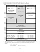
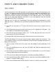
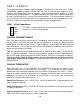
PM12DG128 / PM12DT128 Memory Map
FFFF
Expanded Wide Mode
Special (BDM) Expanded
Wide Mode
Single Chip Mode
C000
1 2
CONFIG ON ON
MODE ON ON
External EPROM
U5/6 (Mon12)
1 2 3 4
CONFIG OFF OFF OFF OFF
MODE OFF OFF
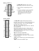
On-Chip Flash Memory
Flash Page
8000 – C000
BFFF
8000
4000
External RAM
U3/4
1 2
CONFIG ON OFF
MODE OFF OFF
(see BDM notes)
External RAM
U3/4
3FFF
2000
On-Chip RAM
3E00 – 3FFF used by Mon12
1FFF
1000
Reserved
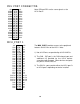
FFF
800
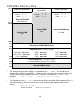
On-Chip EEPROM
Peripheral Area
7FF
400
Unused = 400-7BF
LCD / CS7 = 7F0-7FF
CS6 = 7E0-7EF
CS5 = 7D0-7DF
CS4 = 7C0-7CF
CS3 = 7B0-7BF
CS2 = 7A0-7AF
CS1 = 790-79F
CS0 = 780-78F
3FF
000
Internal Registers
See your MCU Technical Reference Manual
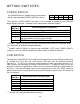
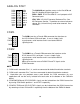
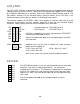
1. The Peripheral Area (A00-BFF) is set to Narrow (8-bit) data width by the debug utilities. If
using this memory, you must also do this in your software when booting from flash as
follows:
MOVW #$0CF0,PEAR
MOVB #$73,MISC ; Flash on, p-sel stretch = 3