
User manual


Chapter 3: Architecture
3
2
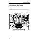
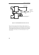
Functional Overview
PowerDAQ PD2-MF/MFS series have very extensive input modes,
clocking and triggering capabilities as well as simultaneous subsystems
operations.
+
-
E
x
t
e
r
n
a
l
A
n
a
l
o
g
I
/
O
C
o
n
n
e
c
t
o
r
(64)
DAC0
DAC1
Voltage
Reference
AOut Calibration
DACs
Analog
Output
Amplifiers
Ext. Aln Conv Clock
Ext. Aln Scan Clock
Ext. Trigger
Aln Clock Out
Aln Control
Bus Master PCI Interface
Motorola 66MHz DSP 56301
E
S
S
I
A
O
u
t
F
I
F
O
A
O
u
t
C
l
o
c
k
6
C
h
a
n
n
e
l
D
M
A
1
2
k
P
r
o
g
r
a
m
R
A
M
1
2
k
D
a
t
a
R
A
M
B
o
o
t
s
t
r
a
p
R
O
M
A
l
n
C
o
n
v
C
l
o
c
k
A
l
n
S
c
a
n
C
l
o
c
k
Voltage
Reference
Aln Calibration
DACs
Custom
PGIA Gain
Amp.
12,14,
16-bit
Sampling
A/D
Converter
Upgradable
1k Sample
ADC
FIFO
Channel/
Gain
Control
Logic
Channel
List
FIFO
Aln Power
Conditioner
16 or 64
Channel
Analog
Multiplexer
Digital
Output
(Driver)
Configuration
& Calibration
EEPROM
32 Bit PCI Bus
C
o
n
t
r
o
l
A
d
d
r
e
s
s
D
a
t
a
(16)
I
n
t
e
r
n
a
l
D
i
g
i
t
a
l
I
/
O
C
o
n
n
e
c
t
o
r
s
J
2
,
J
4
(16)
I
n
t
e
r
b
o
a
r
d
S
y
n
c
h
r
o
n
i
z
a
t
i
o
n
Digital
Input
Buffer
Latch
Interrupt
(4)
UCT Control
DIn Control
DOut Control
AIn Clocking & Triggering
A
d
d
r
e
s
s
Ext. Aln Conv Clock
Ext. Aln Scan Clock
Ext. Trigger
Aln Clock Out
Clock
Gate
Out
3
3
3
User
Counter
Timer
(82C54)
Local Data Bus
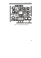
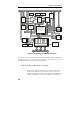
Figure 10: PowerDAQ PD2 Block diagram