
User`s manual


A-1
APPENDIX A:
RS232 Adapter Cables
This appendix provides the information required for connecting an RTU RS232 port to various
units, as detailed below:
• Connection to a computer/terminal (MDLC protocol or User Port)
• Connection to a modem (MDLC protocol or User Port)
• Connection to a radio (MDLC protocol)
• RTU-to-RTU connection using MDLC protocol through RS232 ports (RS-Link)
Connection to a Computer or Terminal
To connect one of the RTU RS232 Ports to a computer/terminal, you should use the FLN6457
adapter, which ends with the female 25-pin or 9-pin, D-type connector. The port may be
defined either as a MDLC protocol port or as a User Port.
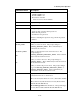
The signals that appear on the female 25-pin or 9-pin D-type connector are according to the
RS232 standard – see the following table. In this case, the RTU serves as DCE (Data
Communication Equipment).
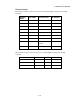
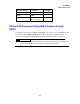
RS232 Function 8-pin Connector
(on RTU)
25-pin
Female
9-pin Female Direction
TX-DATA
2 ←
2 3 from DTE
RX-DATA
1 →
32to DTE
RTS
5 ←
4 7 from DTE
CTS
8 →
58to DTE
DSR
7 →
66to DTE
GND 4 7 5 -
DTR
3 ←
20 4 from DTE
DCD (Rec line)
6 →
81to DTE
To extend the cable, you may use any extension cable with male and female D-type connectors
(connected pin-to-pin, not crossed).
Note: When a User Port is defined as Computer/Terminal with DTR support:
1) The RTU will not transmit unless it receives DTR=ON from the computer/terminal.
2) The RTU will not receive unless it receives RTS=ON from the computer/terminal.