
Processor Users Manual

4-16 MPC8260 PowerQUICC II UserÕs Manual MOTOROLA
Part II. ConÞguration and Reset
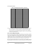
Note that the interrupt vector table differs from the interrupt priority table in only two ways:
¥ FCC, SCC, and MCC vectors are Þxed; they are not affected by the SCC group
mode, spread mode, or the relative priority order of the FCCs, SCCs, and MCC.
¥ An error vector exists as the last entry in Table 4-3. The error vector is issued when
no interrupt is requesting service.
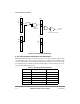
4.2.4.1 Port C External Interrupts
There are 16 external interrupts, coming from the parallel I/O port C pins,PC[0Ð15]. When
ones of these pins is conÞgured as an input, a change according to the SIU external interrupt
control register (SIEXR) causes an interrupt request signal to be sent to the interrupt
controller. PC[0Ð15] lines can be programmed to assert an interrupt request upon any
change. Each port C line asserts a unique interrupt request to the interrupt pending register
and has a different internal interrupt priority level within the interrupt controller.
Requests can be masked independently in the interrupt mask register (SIMR). Notice that
the global SIMR is cleared on system reset so pins left ßoating do not cause false interrupts.
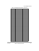
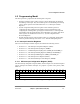
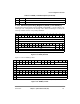
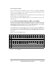
38 SCC4 0b10_1011
39 Reserved 0b10_11xx
40 PC15 0b11_0000
41 PC14 0b11_0001
42 PC13 0b11_0010
43 PC12 0b11_0011
44 PC11 0b11_0100
45 PC10 0b11_0101
46 PC9 0b11_0110
47 PC8 0b11_0111
48 PC7 0b11_1000
49 PC6 0b11_1001
50 PC5 0b11_1010
51 PC4 0b11_1011
52 PC3 0b11_1100
53 PC2 0b11_1101
54 PC1 0b11_1110
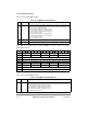
55 PC0 0b11_1111
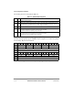
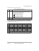
Table 4-3. Encoding the Interrupt Vector (Continued)
Interrupt Number Interrupt Source Description Interrupt Vector