
Processor Users Manual

MOTOROLA Chapter 4. System Interface Unit (SIU) 4-21
Part II. ConÞguration and Reset
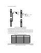
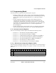
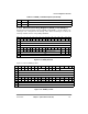
4.3.1.4 SIU Interrupt Pending Registers (SIPNR_H and SIPNR_L)
Each bit in the interrupt pending registers (SIPNR_H and SIPNR_L), shown in Figure 4-14
and Figure 4-15, corresponds to an interrupt source. When an interrupt is received, the
interrupt controller sets the corresponding SIPNR bit.
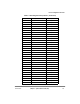
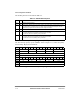
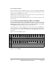
Figure 4-15 shows SIPNR_L Þelds.
3Ð11 YC2PÐYC8P Same as YC1P, but for YCC2ÐYCC8
12Ð15 Ñ Reserved, should be cleared.
Bits 0 1 2 3 4 5 6 7 8 9 10 11 12 13 14 15
Field PC0 PC1 PC2 PC3 PC4 PC5 PC6 PC7 PC8 PC9 PC10 PC11 PC12 PC13 PC14 PC15
Reset UndeÞned (the user should write 1s to clear these bits before using)
R/W R/W
Addr 0x10C08
Bits 16 17 18 19 20 21 22 23 24 25 26 27 28 29 30 31
Field IRQ0 IRQ1 IRQ2 IRQ3 IRQ4 IRQ5 IRQ6 IRQ7 Ñ TMCNT PIT Ñ
Reset UndeÞned (the user should write 1s to clear these bits before using) 0
1
0
1
0
1
R/W R/W
Addr 0x10C10
1
These Þelds are zero after reset because their corresponding mask register bits are cleared (disabled).
Figure 4-14. SIPNR_H Fields
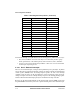
Bits 0 1 2 3 4 5 6 7 8 9 10 11 12 13 14 15
Field FCC1 FCC2 FCC3 Ñ MCC1 MCC2 Ñ SCC1 SCC2 SCC3 SCC4 Ñ
Reset 0000_0000_0000_0000
1
R/W R/W
Addr 0x10C0C
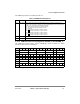
Bits 16 17 18 19 20 21 22 23 24 25 26 27 28 29 30 31
Field I2C SPI RTT SMC1 SMC2 IDMA1 IDMA2 IDMA3 IDMA4 SDMA Ñ TIMER1 TIMER2 TIMER3 TIMER4 Ñ
Reset 0000_0000_0000_000
1
0
1
R/W R/W
Addr 0x10C0E
1
These Þelds are zero after reset because their corresponding mask register bits are cleared (disabled).
Figure 4-15. SIPNR_L Fields
Table 4-7. SCPRR_L Field Descriptions (Continued)
Bits Name Description