
Processor Users Manual

4-25
MPC8260 PowerQUICC II UserÕs Manual
MOTOROLA
Part II. ConÞguration and Reset
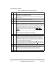
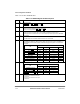
Table 4-8 describes SIEXR Þelds.
4.3.2 System ConÞguration and Protection Registers
The system conÞguration and protection registers are described in the following sections.
4.3.2.1 Bus ConÞguration Register (BCR)
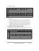
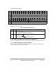
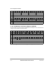
The bus conÞguration register (BCR), shown in Figure 4-21, contains conÞguration bits for
various features and wait states on the 60x bus.
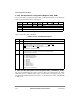
Bits
0 1 2 3 4 5 6 7 8 9 10 11 12 13 14 15
Field
EDPC0 EDPC1 EDPC2 EDPC3 EDPC4 EDPC5 EDPC6 EDPC7 EDPC8 EDPC9 EDPC10 EDPC11 EDPC12 EDPC13 EDPC14 EDPC15
Reset 0000_0000_0000_0000
R/W R/W
Addr 0x10C24
Bit 16 17 18 19 20 21 22 23 24 25 26 27 28 29 30 31
Field EDI0 EDI1 EDI2 EDI3 EDI4 EDI5 EDI6 EDI7 Ñ
Reset 0000_0000_0000_0000
R/W R/W R
Addr 0x10C26
Figure 4-20. SIU External Interrupt Control Register (SIEXR)
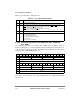
Table 4-8. SIEXR Field Descriptions
Bits Name Description
0Ð15 EDPCx Edge detect mode for port Cx. The corresponding port C line (PCx) asserts an interrupt request
according to the following:
0 Any change on PCx generates an interrupt request.
1 High-to-low change on PCx generates an interrupt request.
16Ð23 EDIx Edge detect mode for IRQ
x
. The corresponding IRQ line (IRQx) asserts an interrupt request
according to the following:
0 Low assertion on IRQ
x
generates an interrupt request.
1 High-to-low change on IRQ
x
generates an interrupt request.