
Processor Users Manual

4-33 MPC8260 PowerQUICC II UserÕs Manual MOTOROLA
Part II. ConÞguration and Reset
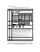
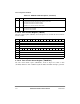
10Ð11 APPC Address parity pins conÞguration. Note that during power on reset the MODCK pins are used for
PLL conÞguration. The pin multiplexing indicated in the table applies only to normal operation.
Selection between IRQ7
and INT_OUT is according to CPU state. If the core is disabled, the pin is
INT_OUT
; otherwise it is IRQ7.
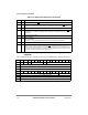
Pin
APPC
00 01 10 11
MODCK1/AP(1)/TC(0)/
BNKSEL(0)
TC(0) AP(1) BNKSEL(0) Ñ
MODCK2/AP(2)/TC(1)/
BNKSEL(1)
TC(1) AP(2) BNKSEL(1)
MODCK3/AP(3)/TC(2)/
BNKSEL(2)
TC(2) AP(3) BNKSEL(2)
IRQ7
/INT_OUT/APE IRQ7/
INT_OUT
APE IRQ7/INT_OUT IRQ7/
INT_OUT
CS11
/AP(0) CS11 AP(0) CS11 Ñ
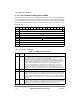
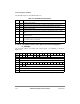
12Ð13 CS10PC Chip select 10-pin conÞguration.
Pin
CS10PC
00 01 10
CS10
/BCTL1/DBG_DIS CS10 BCTL1 DBG_DIS
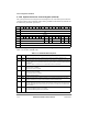
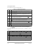
14Ð15 BCTLC Buffer control conÞguration.
00 BCTL0
is used as W/R control. BCTL1 is used as OE control.
01 BCTL0
is used as W/R control. BCTL1 is used as OE control.
10 BCTL0
is used as WE control. BCTL1 is used as RE control.
11 Reserved
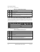
16-17 MMR Mask masters requests. In some systems, several bus masters are active during normal operation;
only one should be active during boot sequence. The active master, which is the boot device,
initializes system memories and devices and enables all other masters. MMR facilitates such a
boot scheme by masking the selected masterÕs bus requests. MMR can be conÞgured through the
hard reset conÞguration sequence see Section 5.4.2, ÒHard Reset ConÞguration Examples.Ó
Typically system conÞguration identiÞes only one master is the boot device, which initializes the
system and then enables all other devices by writing 00 to MMR.
Note: It is not recommended to mask the request of a master which is deÞned as the parked
master in the arbiter, since this cannot prevent this master from getting a bus grant.
00 No masking on bus request lines.
01 Reserved
10 The MPC8260Õs internal core bus request masked and external bus requests two and three
masked (boot master connected to external bus request 1).
11 All external bus requests masked (boot master is the MPC8260Õs internal core).
18 LPBSE Local bus parity byte select enable.
0 Parity byte select is disabled. LGPL4 output of UPM is available for memory control.
1 Parity byte select is enabled. LGPL4 pin is used as local bus parity byte select output from the
MPC8260.
19Ð31 Ñ Reserved, should be cleared.
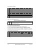
Table 4-12. SIUMCR Register Field Descriptions (Continued)
Bits Name Description