
Processor Users Manual

4-39 MPC8260 PowerQUICC II UserÕs Manual MOTOROLA
Part II. ConÞguration and Reset
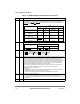
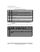
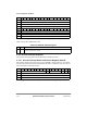
The L_TESCR1 register bits are described in Table 4-17.
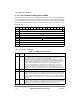
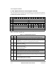
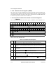
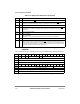
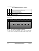
4.3.2.13 Local Bus Transfer Error Status and Control Register 2
(L_TESCR2)
The local bus transfer error status and control register 2 (L_TESCR2) is shown in
Figure 4-34.
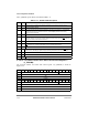
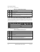
Table 4-17. L_TESCR1 Field Descriptions
Bits Name Description
0 BM Bus monitor time-out. Indicates that TEA
was asserted due to the local bus monitor time-out.
1 Ñ Reserved, should be cleared.
2 PAR Parity error. Indicates that TEA
was asserted due to parity error on the local bus. L_TESCR2[PB]
indicates the byte lane that caused the error and L_TESCR2[BNK] indicates which memory
controller bank was accessed.
3Ð4 Ñ Reserved, should be cleared.
5 WP Write protect error. Indicates that a write was attempted to a local bus memory region that was
deÞned as read-only in the memory controller. Note that this alone does not cause TEA
assertion.
Usually, in this case, the bus monitor will time-out.
6 Ñ Reserved, should be cleared.
7Ð9 TC Transfer code. These bits indicates the transfer code of the local bus transaction that caused the
TEA
. Section 8.4.3.2, ÒTransfer Code Signals TC[0Ð2], describes transfer codes.
10 Ñ Reserved, should be cleared.
11Ð15 TT Transfer type. Indicates the transfer type of the local bus transaction that caused the TEA
.
Section 8.4.3.1, ÒTransfer Type Signal (TT[0Ð4]) Encoding,Ó describes the various transfer types.
16 Ñ Reserved, should be cleared.
17 DMD Data errors disable. Setting this bit disables parity errors on the local bus.
18Ð31 Ñ Reserved, should be cleared.
Bits 0 1 2 3 4 5 6 7 8 9 10 11 12 13 14 15
Field Ñ PB
Reset 0000_0000_0000_0000
R/W R/W
Addr 0x1004C
Bits 16 17 18 19 20 21 22 23 24 25 26 27 28 29 30 31
Field BNK Ñ
Reset 0000_0000_0000_0000
R/W R/W
Addr 0x1004E
Figure 4-34. Local Bus Transfer Error Status and Control Register 2 (L_TESCR2)