
Processor Users Manual

4-40 MPC8260 PowerQUICC II UserÕs Manual MOTOROLA
Part II. ConÞguration and Reset
Table 4-18 describes L_TESCR2 Þelds.
4.3.2.14 Time Counter Status and Control Register (TMCNTSC)
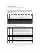
The time counter status and control register (TMCNTSC), shown in Figure 4-35, is used to
enable the different TMCNT functions and for reporting the source of the interrupts. The
register can be read at any time. Status bits are cleared by writing ones; writing zeros does
not affect the value of a status bit.
.
Table 4-19 describes TMCNTSC Þelds.
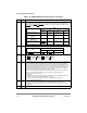
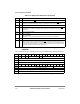
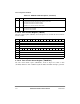
Table 4-18. L_TESCR2 Field Descriptions
Bits Name Description
0Ð11 Ñ Reserved, should be cleared.
12Ð15 PB Parity error on byte. There are four parity error status bits, one per 8-bit lane. A bit is set for the byte
that had a parity error.
16Ð27 BNK Memory controller bank. There are twelve error status bits, one per memory controller bank. A bit is
set for the local bus memory controller bank that had an error. Note that BNK is invalid if the error
was not caused by ECC or PARITY checks.
28Ð31 Ñ Reserved, should be cleared.
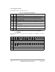
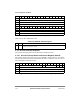
Bits 0 1 2 3 4 5 6 7 8 9 10 11 12 13 14 15
Field Ñ SEC ALR Ñ SIE ALE TCF TCE
Reset 0000_0000_0000_0000
R/W R/W
Addr 0x10220
Figure 4-35. Time Counter Status and Control Register (TMCNTSC)
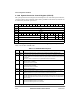
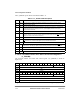
Table 4-19. TMCNTSC Field Descriptions
Bits Name Description
0Ð7 Ñ Reserved, should be cleared.
8 SEC Once per second interrupt. This status bit is set every second and should be cleared by software.
9 ALR Alarm interrupt. This status bit is set when the value of the TMCNT is equal to the value programmed
in the alarm register.
10Ð11 Ñ Reserved, should be cleared.
12 SIE Second interrupt enable.
0 The time counter does not generate an interrupt when SEC is set.
1 The time counter generates an interrupt when SEC is set.
13 ALE Alarm interrupt enable. If ALE = 1, the time counter generates an interrupt when ALR is set.