
Processor Users Manual

4-42 MPC8260 PowerQUICC II UserÕs Manual MOTOROLA
Part II. ConÞguration and Reset
Table 4-20 describes TMCNTAL Þelds.
4.3.3 Periodic Interrupt Registers
The periodic interrupt registers are described in the following sections.
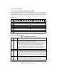
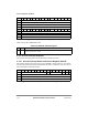
4.3.3.1 Periodic Interrupt Status and Control Register (PISCR)
The periodic interrupt status and control register (PISCR), shown in Figure 4-38, contains
the interrupt request level and the interrupt status bit. It also contains the controls for the 16
bits to be loaded in a modulus counter.
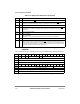
Bits 0 1 2 3 4 5 6 7 8 9 10 11 12 13 14 15
Field ALARM
Reset Ñ
R/W R/W
Addr 0x1022C
Bits 16 17 18 19 20 21 22 23 24 25 26 27 28 29 30 31
Field ALARM
Reset Ñ
R/W R/W
Addr 0x1222E
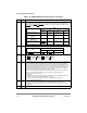
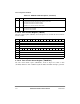
Figure 4-37. Time Counter Alarm Register (TMCNTAL)
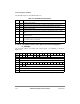
Table 4-20. TMCNTAL Field Descriptions
Bits Name Description
0Ð31 ALARM The alarm interrupt is generated when ALARM Þeld matches the corresponding TMCNT bits. The
resolution of the alarm is 1 second.
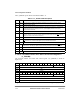
Bits 0 1 2 3 4 5 6 7 8 9 10 11 12 13 14 15
Field Ñ PS Ñ PIE PTF PTE
Reset 0000_0000_0000_0000
R/W R/W
Addr 0x10240
Figure 4-38. Periodic Interrupt Status and Control Register (PISCR)