
Processor Users Manual

4-43 MPC8260 PowerQUICC II UserÕs Manual MOTOROLA
Part II. ConÞguration and Reset
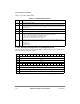
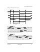
Table 4-21 describes PISCR Þelds.
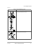
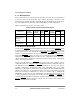
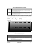
4.3.3.2 Periodic Interrupt Timer Count Register (PITC)
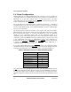
The periodic interrupt timer count register (PITC), shown in Figure 4-39, contains the 16
bits to be loaded in a modulus counter.
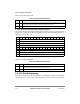
Table 4-21. PISCR Field Descriptions
Bits Name Description
0Ð7 Ñ Reserved, should be cleared.
8 PS Periodic interrupt status. Asserted if the PIT issues an interrupt. The PIT issues an interrupt after the
modulus counter counts to zero. The PS bit can be negated by writing a one to PS. A write of zero has
no effect on this bit.
9Ð12 Ñ Reserved, should be cleared.
13 PIE Periodic interrupt enable. If PIE = 1, the periodic interrupt timer generates an interrupt when PS = 1.
14 PTF Periodic interrupt frequency. The input clock to the periodic interrupt timer may be either 4 MHz or
32 KHz. The user should set the PTF bit according to the frequency of this clock.
0 The input clock to the periodic interrupt timer is 4 MHz.
1 The input clock to the periodic interrupt timer is 32 KHz.
See Section 4.1.2, ÒTimers Clock,Ó for further details
15 PTE Periodic timer enable. This bit controls the counting of the periodic interrupt timer. When the timer is
disabled, it maintains its old value. When the counter is enabled, it continues counting using the
previous value.
0 Disable counter.
1 Enable counter
Bits 0 1 2 3 4 5 6 7 8 9 10 11 12 13 14 15
Field PITC
Reset 0000_0000_0000_0000
R/W R/W
Addr 0x10244
Bits 16 17 18 19 20 21 22 23 24 25 26 27 28 29 30 31
Field Ñ
Reset 0000_0000_0000_0000
R/W R/W
Addr 0x10246
Figure 4-39. Periodic interrupt Timer Count Register (PITC)