
Processor Users Manual


5-4 MPC8260 PowerQUICC II UserÕs Manual MOTOROLA
Part II. ConÞguration and Reset
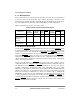
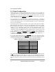
5.2 Reset Status Register (RSR)
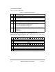
The reset status register (RSR), shown in Figure 5-1, is memory-mapped into the
MPC8260Õs SIU register map.
Table 5-3 describes RSR Þelds.
Bits 0 1 2 3 4 5 6 7 8 9 10 11 12 13 14 15
Field Ñ
R/W R/W
Reset 0000_0000_0000_0000
Addr 0x10C90
Bits
16 17 18 19 20 21 22 23 24 25 26 27 28 29 30 31
Field Ñ JTRS CSRS SWRS BMRS ESRS EHRS
R/W R/W
Reset 0000_0000_0000_0011
Addr 0x10C92
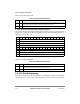
Figure 5-1. Reset Status Register (RSR)
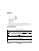
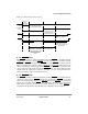
Table 5-3. RSR Field Descriptions
Bits Name Function
0Ð25 Ñ Reserved, should be cleared.
26 JTRS JTAG reset status. When the JTAG reset request is set, JTRS is set and remains set until software
clears it. JTRS is cleared by writing a 1 to it (writing zero has no effect).
0 No JTAG reset event occurred
1 A JTAG reset event occurred
27 CSRS Check stop reset status. When the core enters a checkstop state and the checkstop reset is
enabled by the RMR[CSRE], CSRS is set and it remains set until software clears it. CSRS is
cleared by writing a 1 to it (writing zero has no effect).
0 No enabled check stop reset event occurred
1 An enabled check stop reset event occurred
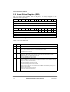
28 SWRS Software watchdog reset status. When a software watchdog expire event (which causes a reset) is
detected, the SWRS bit is set and remains that way until the software clears it. SWRS is cleared by
writing a 1 to it (writing zero has no effect).
0 No software watchdog reset event occurred
1 A software watchdog reset event has occurred
29 BMRS Bus monitor reset status. When a bus monitor expire event (which causes a reset) is detected,
BMRS is set and remains set until the software clears it. BMRS can be cleared by writing a 1 to it
(writing zero has no effect).
0 No bus monitor reset event has occurred
1 A bus monitor reset event has occurred