
Processor Users Manual


MOTOROLA Chapter 8. The 60x Bus 8-19
Part III. The Hardware Interface
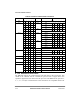
8.4.3.7 60x-Compatible Bus ModeÑSize Calculation
To comply with the requirements listed in Table 8-8 and Table 8-9, the transfer size and a
new address must be calculated at the termination of each beat of a port-size transaction. In
single-MPC8260 bus mode, these calculations are internal and do not constrain the system.
In 60x-compatible bus mode, the external slave or master must determine the new address
and size. Table 8-10 describes the address and size calculation state machine. Note that the
address and size states are for internal use and are not transferred on the address or TSIZ
pins. Extended transactions (16- and 24-byte) are not described here but can be determined
by extending this table for 9-, 10-, 16-, 23-, and 24-byte transactions.
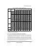
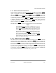
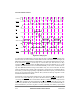
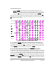
Table 8-9. Data Bus Contents for Write Cycles
Transfer
Size
TSIZ[0Ð3]
Address
State
1
A[29Ð31]
1
Address state is the calculated address for port size
External Data Bus Pattern
0Ð7 8Ð15 16Ð23 24Ð31 32Ð39 40Ð47 48Ð55 56Ð63
Byte
(0001)
000 OP0
2
2
OPn: These lanes are read or written during that bus transaction. OP0 is the most-signiÞcant byte of a word
operand and OP7 is the least-signiÞcant byte.
Ñ
3
3
Ñ Denotes a byte not driven during that write cycle.
ÑÑÑÑÑÑ
001 OP1OP1ÑÑÑÑÑÑ
010 OP2ÑOP2ÑÑÑÑÑ
011 OP3OP3ÑOP3ÑÑÑÑ
100 OP4 Ñ Ñ Ñ OP4 Ñ Ñ Ñ
101 OP5 OP5 Ñ Ñ Ñ OP5 Ñ Ñ
110
1
OP6 Ñ OP6 Ñ Ñ Ñ OP6 Ñ
111 OP7 OP7 Ñ OP7 Ñ Ñ Ñ OP7
Half Word
(0010)
000 OP0OP1ÑÑÑÑÑÑ
001 OP1OP1OP2ÑÑÑÑÑ
010 OP2OP3OP2OP3ÑÑÑÑ
100 OP4 OP5 Ñ Ñ OP4 OP5 Ñ Ñ
101 OP5 OP5 OP6 Ñ Ñ OP5 OP6 Ñ
110 OP6 OP7 OP6 OP7 Ñ Ñ OP6 OP7
Triple Byte
(0011)
000 OP0OP1OP2ÑÑÑÑÑ
001 OP1OP1OP2OP3ÑÑÑÑ
100 OP4 OP5 OP6 Ñ OP4 OP5 OP6 Ñ
101 OP5 OP5 OP6 OP7 Ñ OP5 OP6 OP7
Word
(0100)
000 OP0OP1OP2OP3ÑÑÑÑ
100 OP4 OP5 OP6 OP7 OP4 OP5 OP6 OP7
Double Word
(0000)
000 OP0 OP1 OP2 OP3 OP4 OP5 OP6 OP7