
Processor Users Manual

MOTOROLA Chapter 10. Memory Controller 10-13
Part III. The Hardware Interface
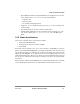
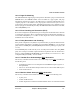
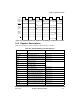
Figure 10-5. Partial Data Valid for 32-Bit Port Size Memory, Double-Word Transfer
10.3 Register Descriptions
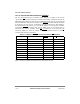
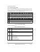
Table 10-2 lists registers used to control the 60x bus memory controller.
Table 10-2. 60x Bus Memory Controller Registers
Abbreviation Name Reference
BR0ÐBR11 Base register banks 0Ð11 Section 10.3.1
OR0ÐOR11] Option register banks 0Ð11 Section 10.3.2
PSDMR 60x bus SDRAM machine mode register Section 10.3.3
LSDMR Local bus SDRAM machine mode register Section 10.3.4
MAMR UPMA mode register Section 10.3.5
MBMR UPMB mode register
MCMR UPMC mode register
MDR Memory data register Section 10.3.6
MAR Memory address register Section 10.3.7
MPTPR Memory refresh timer prescaler register Section 10.3.12
PURT 60x bus assigned UPM refresh timer Section 10.3.8
PSRT 60x bus assigned SDRAM refresh timer Section 10.3.10
LURT Local bus assigned UPM refresh timer Section 10.3.9
LSRT Local bus assigned SDRAM refresh timer Section 10.3.11
TESCRx 60x bus error status and control registers Section 10.3.13
LTESCRx Local bus error status and control regs Section 10.3.14
Clock
External
PSD
VAL
Internal
T
A
Data Bus
Data Bus
(32 msb)
(32 msb)
Upper 4 bytes Lower 4 bytes
Internal
Data Bus
(32 lsb)
Upper 4 bytes
Lower 4 bytes