
Processor Users Manual

10-19 MPC8260 PowerQUICC II UserÕs Manual MOTOROLA
Part III. The Hardware Interface
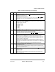
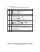
21Ð22 ACS Address to chip select setup. Can be used when the external memory access is handled by the
GPCM. It allows the delay of the CS
assertion relative to the address change.
00 CS
is output at the same time as the address lines
01 Reserved
10 CS
is output a quarter of a clock after the address lines
11 CS
is output half a clock after the address lines
Note: After a system reset, OR0[ACS] = 1.
23 Ñ Reserved, should be cleared.
24Ð27 SCY Cycle length in clocks. Determines the number of wait states inserted in the cycle, when the GPCM.
handles the external memory access. Thus it is the main parameter for determining cycle length. The
total cycle length depends on other timing attribute settings.
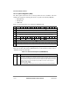
The total memory access length is (2 + SCY) x Clocks.
If the user selects an external PSD
VAL response for this memory bank (by setting the SETA bit),
SCY is not used.
0000 = 0 clock cycle wait states...1111 = 15 clock cycles wait states
Note: After a system reset, OR0[SCY] = 1111.
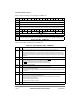
28 SETA External access termination (PSD
VAL generation). Used to specify that when the GPCM is selected
to handle the memory access initiated to this memory region, the access is terminated externally by
asserting the GT
A external pin. In this case, PSDVAL is asserted one clock later on the bus.
0 PSD
VAL is generated internally by the memory controller unless GTA is asserted earlier externally.
1 PSD
VAL is generated after external logic asserts GTA.
Note: After a system reset, the OR0[SETA] is cleared.
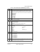
29 TRLX Timing relaxed. Works in conjunction with EHTR (bit 30).
0 Normal timing is generated by the GPCM
1 Relaxed timing is generated by the GPCM for accesses initiated to this memory region.
30 EHTR Extended hold time on read accesses. Indicates with TRLX how many cycles are inserted between a
read access from the current bank and the next access. ORx[29,30] are interpreted as follows:
00 Normal timing is generated by the memory controller. No additional cycles are inserted.
01 One idle clock cycle is inserted.
10 Four idle clock cycles are inserted.
11 Eight idle clock cycles are inserted.
31 Ñ Reserved, should be cleared.
Table 10-5. ORxÑGPCM Mode Field Descriptions (Continued)
Bits Name Description