
Processor Users Manual

MOTOROLA Chapter 10. Memory Controller 10-25
Part III. The Hardware Interface
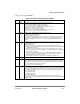
SDRAM DeviceÐSpeciÞc Parameters:
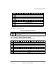
14Ð16 RFRC Refresh recovery. DeÞnes the earliest timing for an activate command after a
REFRESH
command. Sets the refresh recovery interval in clock cycles. See Section 10.4.6.6, ÒRefresh
Recovery Interval (RFRC),Ó for how to set this Þeld.
000 Reserved
001 3 clocks
010 4 clocks
011 5 clocks
100 6 clocks
101 7 clocks
110 8 clocks
111 16 clocks
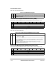
17Ð19 PRETOACT Precharge to activate interval. DeÞnes the earliest timing for
ACTIVATE or REFRESH command
after a precharge command. See Section 10.4.6.1, ÒPrecharge-to-Activate Interval.Ó
001 1 clock-cycle wait states
010 2 clock-cycle wait states
...
111 7 clock-cycle wait states
000 8 clock-cycle wait states
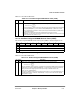
20Ð22 ACTTORW Activate to read/write interval. DeÞnes the earliest timing for
READ/WRITE command after an
ACTIVATE command. See Section 10.4.6.2, ÒActivate to Read/Write Interval.Ó
001 1 clock cycle
010 2 clock cycles
...
111 7 clock cycles
000 8 clock cycles
23 BL Burst length
0 SDRAM burst length is 4. Use this value if the device port size is16
1 SDRAM burst length is 8. Use this value if the device port size is 32 or 8
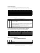
24Ð25 LDOTOPRE Last data out to precharge. DeÞnes the earliest timing for
PRECHARGE command after the last
data was read from the SDRAM. See Section 10.4.6.4, ÒLast Data Out to Precharge.Ó
00 0 clock cycles
01 -1 clock cycle
10 -2 clock cycles
11 Reserved
26Ð27 WRC Write recovery time. DeÞnes the earliest timing for
PRECHARGE command after the last data is
written to the SDRAM. See Section 10.4.6.5, ÒLast Data In to PrechargeÑWrite Recovery.Ó
01 1 clock cycles
10 2 clock cycles
11 3 clock cycles
00 4 clock cycles
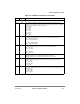
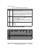
Table 10-8. LSDMR Field Descriptions (Continued)
Bits Name Description