
Processor Users Manual

10-30 MPC8260 PowerQUICC II UserÕs Manual MOTOROLA
Part III. The Hardware Interface
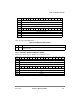
Table 10-11 describes MAR Þelds.
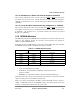
10.3.8 60x Bus-Assigned UPM Refresh Timer (PURT)
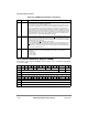
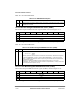
The 60x bus assigned UPM refresh timer register (PURT) is shown in Figure 10-14.
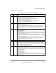
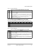
Table 10-12 describes PURT Þelds.
10.3.9 Local Bus-Assigned UPM Refresh Timer (LURT)
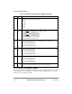
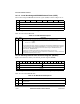
The local bus assigned UPM refresh timer register (LURT) is shown in Figure 10-15.
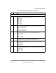
Table 10-11. MAR Field Description
Bits Name Description
0Ð31 A Memory address. The memory address register can be output to the address lines under control of
the AMX bits in the UPM
Bit 0 1 2 3 4 5 6 7
Field PURT
Reset 0000_0000
R/W R/W
Addr 0x10198
Figure 10-14. 60x Bus-Assigned UPM Refresh Timer (PURT)
Table 10-12. 60x Bus-Assigned UPM Refresh Timer (PURT)
Bits Name Description
0Ð7 PURT Refresh timer period. Determines the timer period according to the following equation:
This timer generates a refresh request for all valid banks that selected a UPM machine assigned to
the 60x bus (MxMR[BSEL] = 0) and is refresh-enabled (MxMR[RFEN] = 1). Each time the timer
expires, a qualiÞed bank generates a refresh request using the selected UPM. The qualiÞed banks
are rotating their requests.
Example: For a 25-MHz SYSTEM CLOCK and a required service rate of 15.6 µs, given
MPTPR[PTP] = 32, the PURT value should be 12 decimal. 12/(25 MHz/32) = 15.36 µs, which is less
than the required service period of 15.6 µs.
Bit 0 1 2 3 4 5 6 7
Field LURT
Reset 0000_0000
R/W R/W
Addr 0x101A0
Figure 10-15. Local Bus-Assigned UPM Refresh Timer (LURT)
TimerPeriod
PURT
F
MPTC
-----------------
èø
æö
=