
Processor Users Manual

MOTOROLA Chapter 10. Memory Controller 10-69
Part III. The Hardware Interface
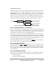
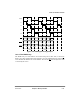
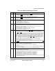
Figure 10-60. UPM Signals Timing Example
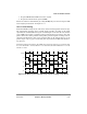
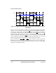
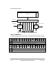
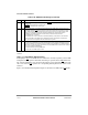
10.6.4 The RAM Array
The RAM array for each UPM is 64 locations deep and 32 bits wide, as shown in
Figure 10-61. The signals at the bottom of Figure 10-61 are UPM outputs. The selected CS
is for the bank that matches the current address. The selected BS is for the byte lanes read
or written by the access.
CSx
GPL1
GPL2
CST1 CST2 CST3 CST4 CST1 CST2 CST3 CST4
G1T1 G1T3
Word 1 Word 2
CLKIN
T1
T2
T3
T4
G1T1 G1T3
G2T1 G2T3
G2T1 G2T3