
Processor Users Manual

10-70 MPC8260 PowerQUICC II UserÕs Manual MOTOROLA
Part III. The Hardware Interface
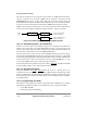
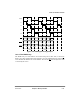
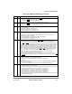
Figure 10-61. RAM Array and Signal Generation
10.6.4.1 RAM Words
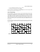
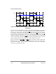
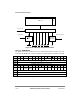
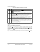
The RAM word, shown in Figure 10-62, is a 32-bit microinstruction stored in one of 64
locations in the RAM array. It speciÞes timing for external signals controlled by the UPM.
Bit 0 1 2 3 4 5 6 7 8 9 10 11 12 13 14 15
Field CST1 CST2 CST3 CST4 BST1 BST2 BST3 BST4 G0L G0H G1T1 G1T3 G2T1 G2T3
Reset Ñ
R/W R/W
Addr (MCR[MAD] indirect addressing of 1 of 64 entries
Bit 16 17 18 19 20 21 22 23 24 25 26 27 28 29 30 31
Field G3T1 G3T3 G4T1/
DLT3
G4T3/
WAEN
G5T1 G5T3 REDO LOOP EXEN AMX NA UTA TODT LAST
Reset Ñ
R/W R/W
Addr (All 32 bits of the RAM word are addressed as shown in the address row above.)
Figure 10-62. The RAM Word
T1, T2, T3, T4
GPL0 GPL2 GPL3 GPL4 GPL5
External Signals Timing Generator (60x or Local)
RAM Array
CS Line
Selector
Byte Select
Packaging
CS
[0Ð11] BS
Current Bank
TSIZ, PS, A[30,31]
32 Bits
64
GPL1