
Processor Users Manual

MOTOROLA Chapter 13. Communications Processor Module Overview 13-9
Part IV. Communications Processor Module
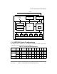
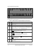
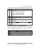
13.3.7 RISC Time-Stamp Control Register (RTSCR)
The RISC time-stamp control register (RTSCR), shown in Figure 13-4, conÞgures the
RISC time-stamp timer (RTSR). The time-stamp timer is used by the ATM and the HDLC
controllers. For application examples, see Section 29.5.3, ÒABR Flow Control Setup,Ó and
Section 31.6, ÒHDLC Mode Register (FPSMR).Ó
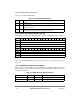
16Ð18 ERAM Enable RAM microcode. ConÞgure as instructed in the download process of a Motorola-supplied
RAM microcode package.
000 Disable microcode program execution from the dual-port RAM.
001 Microcode uses the Þrst 2 Kbytes of the dual-port RAM.
010 Microcode uses the Þrst 4 Kbytes of the dual-port RAM.
011 Microcode uses the Þrst 6 Kbytes of the dual-port RAM.
100 Microcode uses the Þrst 8 Kbytes of the dual-port RAM.
101 Microcode uses the Þrst 10 Kbytes of the dual-port RAM.
110 Microcode uses the Þrst 12 Kbytes of the dual-port RAM.
111 Reserved
19 Ñ Reserved
20, 21,
22, 23
EDMx Edge detect mode. DREQ
x asserts as follows:
0 Low-to-high change
1 High-to-low change
28 DEM12 Edge detect mode for DONE[1, 2]
for IDMA[1, 2]. See Section 18.7.2, ÒDONEx.Ó DONE[1, 2]
asserts as follows:
0 High-to-low change
1 Low-to-high change
29 DEM34 Edge detect mode for DONE[3, 4]
for IDMA[3, 4]. See Section 18.7.2, ÒDONEx.Ó DONE[3, 4]
asserts as follows:
0 High-to-low change
1 Low-to-high change
Bits 0 1 2 3 4 5 6 7 8 9 10 11 12 13 14 15
Field Ñ RTE RTPS (Timer Prescale)
Reset 0000_0000_0000_0000
R/W R/W
Addr 0x119DC
Figure 13-4. RISC Time-Stamp Control Register (RTSCR)
Table 13-3. RISC Controller Configuration Register Field Descriptions (Continued)
Bits Name Description