
Processor Users Manual

MOTOROLA Chapter 13. Communications Processor Module Overview 13-11
Part IV. Communications Processor Module
13.4 Command Set
The core issues commands to the CP by writing to the CP command register (CPCR). The
CPCR rarely needs to be accessed. For example, to terminate the transmission of an SCCÕs
frame without waiting until the end, a
STOP TX command must be issued through the CP
command register (CPCR).
13.4.1 CP Command Register (CPCR)
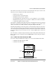
The core should set CPCR[FLG], shown in Figure 13-6, when it issues a command and the
CP clears FLG after completing the command, thus indicating to the core that it is ready for
the next command. Subsequent commands to the CPCR can be given only after FLG is
clear. However, the software reset command issued by setting RST does not depend on the
state of FLG, but the core should still set FLG when setting RST.
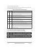
Table 13-6 describes CPCR Þelds.
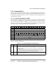
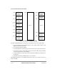
Bits 0 1 2 3 4 5 6 7 8 9 10 11 12 13 14 15
Field RST PAGE Sub-block code (SBC) Ñ FLG
Reset 0000_0000_0000_0000
R/W R/W
Addr 0x119CE
Bits 16 17 18 19 20 21 22 23 24 25 26 27 28 29 30 31
Field Ñ MCC channel number (MCN) Ñ OPCODE
Reset 0000_0000_0000_0000
R/W R/W
Addr 0x119D0
Figure 13-6. CP Command Register (CPCR)
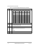
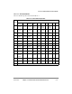
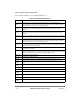
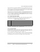
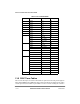
Table 13-6. CP Command Register Field Descriptions
Bit Name Description
0 RST Software reset command. Set by the core and cleared by the CP. When this command is
executed, RST and FLG bit are cleared within two general system clocks. The CPM reset routine
is approximately 60 clocks long, but the user can begin initialization of the CPM immediately after
this command is issued.
RST is useful when the core wants to reset the registers and parameters for all the channels
(FCCs, SCCs, SMCs, SPI, I
2
C, MCC) as well as the CP and RISC timer tables. However, this
command does not affect the serial interface (SIx) or parallel I/O registers.
1Ð5 PAGE Indicates the parameter RAM page number associated with the sub-block being served. See the
SBC description for page numbers.