
Processor Users Manual

18-18 MPC8260 PowerQUICC II UserÕs Manual MOTOROLA
Part IV. Communications Processor Module
18.8.2.1 DMA Channel Mode (DCM)
The IDMA channel mode (DCM) is a 16-bit Þeld within the IDMA parameter RAM, that
controls the operation modes of the IDMA channel. As are all other IDMA parameters, the
DCM is undeÞned at reset.
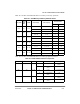
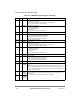
Table 18-5 describes DCM bits.
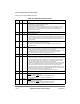
bits 0 1 2 3 4 5 6 7 8 9 10 11 12 13 14 15
Þeld FB LP Ñ TC2 Ñ DMA_WRAP SINC DINC ERM DT S/D
Reset Ñ
R/W R/W
Figure 18-8. DCM Parameters
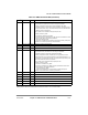
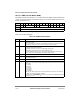
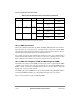
Table 18-5. DCM Field Descriptions
Bits Name Description
0 FB Fly-by mode. See Table 18-6.
0 Dual-address mode.
1 Fly-by (single-address) mode. The internal IDMA transfer buffer is not used. Valid only in
peripheral-to-memory (S/D=10) or memory-to-peripheral (S/D=01) modes.
1 LP Low priority. Applies to memory-to-memory accesses only. See Section 4.3.2, ÒSystem
ConÞguration and Protection Registers.Ó
0 The IDMA transaction to memory is in middle CPM request priority.
1 The IDMA transaction to memory is in low CPM request priority.
Note that IDMA single-address (ßy-by) transfers with external peripherals are always high
priority, ignoring this bit and bypassing other pending SDMA requests.
2Ð4 Ñ Reserved, should be cleared.
5 TC2 Driven on TC[2] during IDMA transactions. The TC[0Ð1] signals are always driven to 0b11
during IDMA transactions.
6 Ñ Reserved, should be cleared.
7Ð9 DMA_WRAP DMA wrap. DeÞnes the size of the IDMA transfer buffer. The IDMA pointer wraps to the
beginning of the buffer whenever DMA_WRAP bytes have been transferred to/from the buffer.
000 64 byte
001 128 byte
010 256 byte
011 512 byte
100 1024 byte
101 2048 byte
11x Reserved
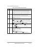
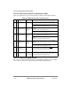
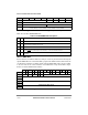
Table 18-7 and Table 18-8 describes the relations between the parameterÕs initial value and
SS_MAX, STS, DTD and DCM[S/D] parameters.
The IDMA transfer buffer (DPR_BUF) size should be consistent with DCM[DMA_WRAP]; that
is DPR_BUF = 64 X 2
(DMA_WRAP)
- 32