
Processor Users Manual

18-23 MPC8260 PowerQUICC II UserÕs Manual MOTOROLA
Part IV. Communications Processor Module
Table 18-9 describes IDSR/IDMR Þelds.
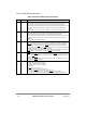
18.8.5 IDMA BDs
Source addresses, destination addresses, and byte counts are presented to the CP using the
special IDMA BDs. The CP reads the BDs, programs the SDMA channel, and notiÞes the
core about the completion of a buffer transfer using the IDMA BDs. This concept is similar
to the one used for the serial controllers on the MPC8260 except that the BD is larger
because it contains additional information.
Bits 0 1 2 3 4 5 6 7
Field Ñ SC OB EDN BC
Reset 0000_0000
R/W R R/W
Addr 0x11020 (IDSR1), 0x11028 (IDSR2), 0x11030 (IDSR3), 0x11038 (IDSR4)/
0x11024 (IDMR1), 0x1102C (IDMR2), 0x11034 (IDMR3), 0x1103C (IDMR4)
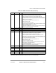
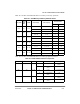
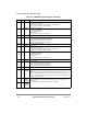
Figure 18-9. IDMA Event/Mask Registers (IDSR/IDMR)
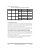
Table 18-9. IDSR/IDMR Field Descriptions
Bits Name Description
0Ð3 Ñ Reserved, should be cleared.
4 SC Stop completed. Set after the IDMA channel completes processing the
STOP_IDMA command. Do not
change channel parameters until SC is set.
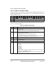
5 OB Out of buffers. Set to indicate that the IDMA channel encountered no valid BDs for the transfer.
6 EDN External DONE
was asserted by device. Set to indicate that the IDMA channel terminated a transfer
because D
ONE was asserted by an external device, on the former SDMA transaction.
7 BC BD completed. Set only after all data of a BD whose I (interrupt) bit is set has completed transfer to the
destination.
0 1 2 3 4 5 6 7 8 9 10 11 12 13 14 15
Offset + 0 V Ñ WILÑ CM Ñ SDN DDN DGBL DBO Ñ DDTB
Offset + 2 Ñ SGBL SBO Ñ SDTB Ñ
Offset + 4 Data Length
Offset + 6
Offset + 8 Source Data Buffer Pointer
Offset + A
Offset + C Destination Data Buffer Pointer
Offset + E
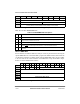
Figure 18-10. IDMA BD Structure