
Processor Users Manual

MOTOROLA Chapter 20. SCC UART Mode 20-5
Part IV. Communications Processor Module
20.5 Data-Handling Methods: Character- or Message-
Based
An SCC UART controller uses the same BD table and buffer structures as the other
protocols and supports both multibuffer, message-based and single-buffer, character-based
operation.
For character-based transfers, each character is sent with stop bits and parity and received
into separate 1-byte buffers. A maskable interrupt is generated when each buffer is received.
In a message-based environment, transfers can be made on entire messages rather than on
individual characters. To simplify programming and save processor overhead, a message is
transferred as a linked list of buffers without core intervention. For example, before
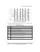
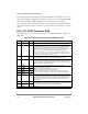
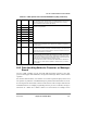
0x4E TOSEQ Hword Transmit out-of-sequence character. Inserts out-of-sequence characters, such as
XOFF and XON, into the transmit stream. The TOSEQ character is put in the Tx
FIFO without affecting a Tx buffer in progress. See Section 20.11, ÒInserting
Control Characters into the Transmit Data Stream.Ó
0x50 CHARACTER1 Hword Control character 1Ð8. These characters deÞne the Rx control characters on which
interrupts can be generated.
0x52 CHARACTER2 Hword
0x54 CHARACTER3 Hword
0x56 CHARACTER4 Hword
0x58 CHARACTER5 Hword
0x5A CHARACTER6 Hword
0x5C CHARACTER7 Hword
0x5E CHARACTER8 Hword
0x60 RCCM Hword Receive control character mask. Used to mask comparison of CHARACTER1Ð8
so classes of control characters can be deÞned. A one enables the comparison,
and a zero masks it.
0x62 RCCR Hword Receive control character register. Used to hold the last rejected control character
(not written to the Rx buffer). Generates a maskable interrupt. If the core does not
process the interrupt and read RCCR before a new control character arrives, the
previous control character is overwritten.
0x64 RLBC Hword Receive last break character. Used in synchronous UART when PSMR[RZS] = 1;
holds the last break character pattern. By counting zeros in RLBC, the core can
measure break length to a one-bit resolution. Read RLBC by counting the zeros
written from bit 0 to where the Þrst one was written. RLBC = 0b001xxxxxxxxxxxxx
indicates two zeros; 0b1xxxxxxxxxxxxxxx indicates no zeros.
Note that RLBC can be used in combination with BRKLN above to calculate the
number of bits in the break sequence: (BRKLN * character length) + (number of
zeros in RLBC).
1
From SCC base. See Section 19.3.1, ÒSCC Base Addresses.Ó
Table 20-1. UART-Specific SCC Parameter RAM Memory Map (Continued)