
Processor Users Manual

21-8 MPC8260 PowerQUICC II UserÕs Manual MOTOROLA
Part IV. Communications Processor Module
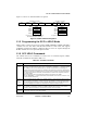
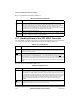
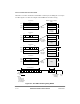
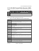
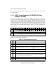
21.9 SCC HDLC Receive Buffer Descriptor (RxBD)
The CP uses the RxBD, shown in Figure 21-4, to report on data received for each buffer.
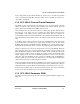
6 RTE Retransmit enable.
0 No retransmission.
1 Automatic frame retransmission is enabled. Particularly useful in the HDLC bus protocol and ISDN
applications where multiple HDLC controllers can collide. Note that retransmission occurs only if a
lost CTS
occurs on the Þrst or second buffer of the frame.
7 Ñ Reserved, should be cleared.
8 FSE Flag sharing enable. Valid only if GSMR_H[RTSM] = 1. Can be modiÞed on-the-ßy.
0 Normal operation.
1 If NOF[0Ð3] = 0b0000, a single shared ßag is sent between back-to-back frames. Other values of
NOF[0Ð3] are decremented by 1. Useful in signaling system #7 applications.
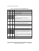
9 DRT Disable receiver while transmitting.
0 Normal operation.
1 As the SCC sends data, the receiver is disabled and gated by the internal R
TS. This helps if the
HDLC channel is on a multidrop line and the SCC does not need to receive its own transmission.
10 BUS HDLC bus mode.
0 Normal HDLC operation.
1 HDLC bus operation is selected. See Section 21.14, ÒHDLC Bus Mode with Collision Detection.Ó
11 BRM HDLC bus R
TS mode. Valid only if BUS = 1. Otherwise, it is ignored.
0 Normal R
TS operation during HDLC bus mode. RTS is asserted on the Þrst bit of the Tx frame and
negated after the Þrst collision bit is received.
1 Special R
TS operation during HDLC bus mode. RTS is delayed by one bit with respect to the
normal case, which helps when the HDLC bus protocol is being run locally and sent over a long-
distance line at the same time. The one-bit delay allows R
TS to be used to enable the transmission
line buffers so that the electrical effects of collisions are not sent over the transmission line.
12 MFF Multiple frames in Tx FIFO. The receiver is not affected.
0 Normal operation. The Tx FIFO must never contain more than one HDLC frame. The CTS
lost
status is reported accurately on a per-frame basis.
1 The Tx FIFO can hold multiple frames, but lost CTS
may not be reported on the buffer/frame it
occurred on. This can improve performance of HDLC transmissions of small back-to-back frames or
when the number of ßags between frames should be limited.
13Ð15 Ñ Reserved, should be cleared.
0 1 2 3 4 5 6 7 8 9 10 11 12 13 14 15
Offset + 0 E Ñ WI LFCM Ñ DE Ñ LG NO AB CR OV CD
Offset + 2 Data Length
Offset + 4 Rx Buffer Pointer
Offset + 6
Figure 21-4. SCC HDLC Receive Buffer Descriptor (RxBD)
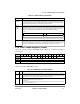
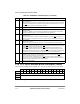
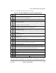
Table 21-6. PSMR HDLC Field Descriptions (Continued)
Bits Name Description