
Processor Users Manual

22-4 MPC8260 PowerQUICC II UserÕs Manual MOTOROLA
Part IV. Communications Processor Module
GSMR[MODE] determines the protocol for each SCC. The SYN1ÐSYN2 synchronization
characters are programmed in the DSR (see Section 19.1.3, ÒData Synchronization
Register (DSR).Ó) The BISYNC controller uses the same basic data structure as other
modes; receive and transmit errors are reported through their respective BDs. There are two
basic ways to handle BISYNC channels:
¥ The controller can inspect data on a per-byte basis and interrupt the core each time
a byte is received.
¥ The controller can be programmed so software handles the Þrst two or three bytes.
The controller directly handles subsequent data without interrupting the core.
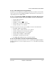
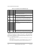
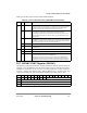
Table 22-1. SCC BISYNC Parameter RAM Memory Map
Offset
1
1
From SCCx base address. See Section 19.3.1, ÒSCC Base Addresses.Ó
Name Width Description
0x30 Ñ Word Reserved
0x34 CRCC Word CRC constant temp value.
0x38 PRCRC Hword Preset receiver/transmitter CRC16/LRC. These values should be preset to all
ones or zeros, depending on the BCS used.
0x3A PTCRC Hword
0x3C PAREC Hword Receive parity error counter. This 16-bit (modulo 2
16
) counter maintained by the
CP counts parity errors on receive if the parity feature of BISYNC is enabled.
Initialize PAREC while the channel is disabled.
0x3E BSYNC Hword BISYNC SYNC register. Contains the value of the SYNC to be sent as the second
byte of a DLEÐSYNC pair in an underrun condition and stripped from incoming
data on receive once the receiver synchronizes to the data using the DSR and
SYN1ÐSYN2 pair. See Section 22.7, ÒBISYNC SYNC Register (BSYNC).Ó
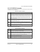
0x40 BDLE Hword BISYNC DLE register. Contains the value to be sent as the Þrst byte of a DLEÐ
SYNC pair and stripped on receive. See Section 22.8, ÒSCC BISYNC DLE
Register (BDLE).Ó
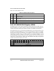
0x42 CHARACTER1 Hword Control character 1Ð8. These values represent control characters that the
BISYNC controller recognizes. See Section 22.6, ÒSCC BISYNC Control
Character Recognition.Ó
0x44 CHARACTER2 Hword
0x46 CHARACTER3 Hword
0x48 CHARACTER4 Hword
0x4A CHARACTER5 Hword
0x4C CHARACTER6 Hword
0x4E CHARACTER7 Hword
0x50 CHARACTER8 Hword
0x52 RCCM Hword Receive control character mask. Masks CHARACTERn comparison so control
character classes can be deÞned. Setting a bit enables and clearing a bit masks
comparison. See Section 22.6, ÒSCC BISYNC Control Character Recognition.Ó