
Processor Users Manual


MOTOROLA Chapter 23. SCC Transparent Mode 23-13
Part IV. Communications Processor Module
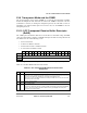
23.13 SCC Status Register in Transparent Mode
(SCCS)
The SCC status register (SCCS) allows monitoring of real-time status conditions on the
RXD line. The real-time status of CTS
and CD are part of the parallel I/O.
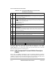
Table 23-10 describes SCCS Þelds.
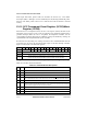
23.14 SCC2 Transparent Programming Example
The following initialization sequence enables the transmitter and receiver, which operate
independently of each other. They implement the connection shown on MPC8260(B) in
Figure 23-1.
The transmit and receive clocks are externally provided to MPC8260(B) using CLK3.
SCC2 is used. The transparent controller is conÞgured with the R
TS2 and CD2 pins active
and CTS2
is conÞgured to be grounded internally. A 16-bit CRC-CCITT is sent with each
transparent frame. The FIFOs are conÞgured for fast operation.
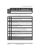
13 BSY Busy condition. Set when a byte or word is received and discarded due to a lack of buffers. The
receiver resumes reception after it gets an
ENTER HUNT MODE command.
14 TXB Tx buffer. Set no sooner than when the last bit of the last byte of the buffer begins transmission,
assuming L is set in the TxBD. If it is not, TXB is set when the last byte is written to the transmit FIFO.
15 RXB Rx buffer. Set when a complete buffer was received on the SCC channel, no sooner than two serial
clocks after the last bit of the last byte in which the buffer is received on RXD.
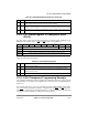
Bit 0 1 2 3 4 5 6 7
Field Ñ CS Ñ
Reset 0000_0000
R/W R
Address 0x11A17 (SCCS1); 0x11A37 (SCCS2); 0x11A57 (SCCS3); 0x11A77 (SCCS4)
Figure 23-5. SCC Status Register in Transparent Mode (SCCS)
Table 23-10. SCCS Field Descriptions
Bit Name Description
0Ð5 Ñ Reserved, should be cleared.
6 CS Carrier sense (DPLL). Shows the real-time carrier sense of the line as determined by the DPLL.
0 The DPLL does not sense a carrier.
1 The DPLL senses a carrier.
7 Ñ Reserved, should be cleared.
Table 23-9. SCCE/SCCM Field Descriptions (Continued)
Bit Name Description