
Processor Users Manual

24-8 MPC8260 PowerQUICC II UserÕs Manual MOTOROLA
Part IV. Communications Processor Module
24.7 SCC Ethernet Parameter RAM
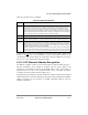
For Ethernet mode, the protocol-speciÞc area of the SCC parameter RAM is mapped as in
Table 24-1.
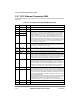
Table 24-1. SCC Ethernet Parameter RAM Memory Map
Offset
1
Name Width Description
0x30 C_PRES Word Preset CRC. For the 32-bit CRC-CCITT, initialize to 0xFFFFFFFF.
0x34 C_MASK Word Constant mask for CRC. For the 32-bit CRC-CCITT, initialized to 0xDEBB20E3.
0x38 CRCEC Word CRC error, alignment error, and discard frame counters. The CPM maintains these
32-bit (modulo 2
32
) counters that can be initialized while the channel is disabled.
CRCEC is incremented for each received frame with a CRC error, not including
frames not addressed to the controller, frames received in the out-of-buffers
condition, frames with overrun errors, or frames with alignment errors. ALEC is
incremented for frames received with dribbling bits, but does not include frames
not addressed to the controller, frames received in the out-of-buffers condition, or
frames with overrun errors. DISFC is incremented for frames discarded because of
the out-of-buffers condition or an overrun error. The CRC does not have to be
correct for DISFC to be incremented.
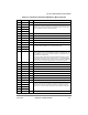
0x3C ALEC
0x40 DISFC
0x44 PADS Hword Short frame PAD character. Write the pad character pattern to be sent when short
frame padding is implemented into PADS. The pattern may be of any value, but
both the high and low bytes should be the same.
0x46 RET_LIM Hword Retry limit. Number of retries (typically 15 decimal) that can be made to send a
frame. An interrupt can be generated if the limit is reached.
0x48 RET_CNT Hword Retry limit counter. Temporary down-counter for counting retries.
0x4A MFLR Hword Maximum frame length register (Typically 1518 decimal). The Ethernet controller
checks the length of an incoming Ethernet frame against this limit. If it is exceeded,
the rest of the frame is discarded and LG is set in the last BD of that frame. The
controller reports frame status and length in the last BD. MFLR is defined as all in-
frame bytes between the start frame delimiter and the end of the frame.
0x4C MINFLR Hword Minimum frame length register. The Ethernet controller checks the incoming
frameÕs length against MINFLR (typically 64 decimal). If the received frame is
smaller than MINFLR, it is discarded unless PSMR[RSH] is set, in which case, SH
is set in the last BD for the frame. For transmitting a frame that is too short, the
Ethernet controller pads the frame to make it MINFLR bytes long, depending on
how PAD is set in the TxBD and on the PAD value in the parameter RAM.
0x4E MAXD1 Hword Max DMAn length register. Gives the option to stop system bus writes after a
frame exceeds a certain size. However, this value is valid only if an address match
is found. The Ethernet controller checks the length of an incoming Ethernet frame
against this user-defined value (usually 1520 decimal). If this limit is exceeded, the
rest of the incoming frame is discarded. The Ethernet controller waits until the end
of the frame or until MFLR bytes are received and reports the frame status and the
frame length in the last RxBD.
MAXD1 is used when an address matches an individual or group address. MAXD2
is used in promiscuous mode when no address match is detected. In a monitor
station, MAXD2 can be much less than MAXD1 to receive entire frames
addressed to this station, but only the headers of the other frames are received.
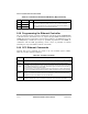
0x50 MAXD2 Hword
0x52 MAXD Hword Rx max DMA.
0x54 DMA_CNT Hword Rx DMA counter. A temporary down-counter used to track frame length.