
Processor Users Manual

MOTOROLA Chapter 26. Serial Management Controllers (SMCs) 26-5
Part IV. Communications Processor Module
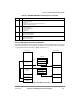
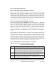
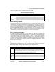
26.2.2 SMC Buffer Descriptor Operation
In UART and transparent modes, the SMCÕs memory structure is like the SCCÕs, except that
SMC-associated data is stored in buffers. Each buffer is referenced by a BD and organized
in a BD table located in the dual-port RAM. See Figure 26-3.
Figure 26-3. SMC Memory Structure
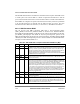
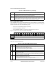
10Ð11 SM SMC mode.
00 GCI or SCIT support.
01 Reserved.
10 UART (must be selected for SMC UART operation).
11 Totally transparent operation.
12Ð13 DM Diagnostic mode.
00 Normal operation.
01 Local loopback mode.
10 Echo mode.
11 Reserved.
14 TEN SMC transmit enable.
0 SMC transmitter disabled.
1 SMC transmitter enabled.
15 REN SMC receive enable.
0 SMC receiver disabled.
1 SMC receiver enabled.
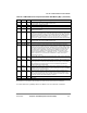
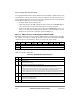
Table 26-1. SMCMR1/SMCMR2 Field Descriptions (Continued)
Bits Name Description
Status and Control
Data Length
Buffer Pointer
Pointer to SMCx
TxBD Table
Pointer to SMCx
RxBD Table
SMC RxBD
Tabl e
SMC TxBD
Ta b l e
Dual-Port RAM
Status and Control
Data Length
Buffer Pointer
Tx Data Buffer
External Memory
RxBD Table
TxBD Table
Rx Data Buffer