
Processor Users Manual

MOTOROLA Chapter 26. Serial Management Controllers (SMCs) 26-33
Part IV. Communications Processor Module
Table 26-20 describes SMC monitor channel TxBD Þelds.
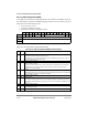
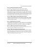
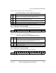
26.5.7 SMC GCI C/I Channel RxBD
The CP uses this BD to report information about the C/I channel receive byte.
Table 26-21 describes SMC C/I channel RxBD Þelds
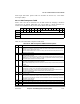
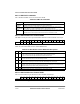
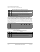
26.5.8 SMC GCI C/I Channel TxBD
The CP uses this BD to report about the C/I channel transmit byte.
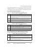
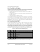
Table 26-20. SMC Monitor Channel TxBD Field Descriptions
Bits Name Description
0 R Ready.
0 Cleared by the CP after transmission. The TxBD is now available to the core.
1 Set by the core when the data byte associated with this BD is ready for transmission.
1 L Last (EOM). Valid only for monitor channel protocol. When L = 1, the SMC Þrst transmits the buffer
data and then transmits the EOM indication on the E bit.
2 AR Abort request. Valid only for monitor channel protocol. Set by the SMC when an abort request is
received on the A bit. The transmitter sends the EOM on the E bit after receiving an abort request.
3Ð7 Ñ Reserved, should be cleared.
8Ð15 DATA Data Þeld. Contains the data to be sent by the SMC on the monitor channel.
0 1 2 3 4 5 6 7 8 9 10 11 12 13 14 15
Offset + 0 E Ñ C/I DATA Ñ
Figure 26-17. SMC C/I Channel RxBD
Table 26-21. SMC C/I Channel RxBD Field Descriptions
Bits Name Description
0 E Empty.
0 Cleared by the CP to indicate that the byte associated with this BD is available to the core.
1 The core sets E to indicate that the byte associated with this BD has been read.
Note that additional data received is discarded until E bit is set.
1Ð7 Ñ Reserved, should be cleared.
8Ð13 C/I DATA Command/indication data bits. For C/I channel 0, bits 10Ð13 contain the 4-bit data Þeld and bits 8Ð
9 are always written with zeros. For C/I channel 1, bits 8Ð13 contain the 6-bit data Þeld.
14Ð15 Ñ Reserved, should be cleared.
0 1 2 3 4 5 6 7 8 9 10 11 12 13 14 15
Offset + 0 R Ñ C/I DATA Ñ
Figure 26-18. SMC C/I Channel TxBD