
Processor Users Manual

MOTOROLA Chapter 27. Multi-Channel Controllers (MCCs) 27-7
Part IV. Communications Processor Module
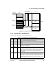
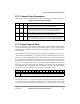
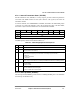
Figure 27-4. Receiver Super Channel with Slot Synchronization Example
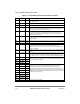
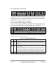
The example in Figure 27-5 shows a receiver super channel without slot synchronization.
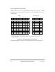
Figure 27-5. Receiver Super Channel without Slot Synchronization Example
0 1 2 3Ð10 11Ð13 14 15
MCC LOOP SUPER MCSEL CNT BYT LST
SI RAM Address
1000x0
0x1
1 0 Regular Channel
1010x1
0x0
1
1
First slot of the super channel
1 0 Super Channel 1
1010x2
0x0
1
1 0 Super Channel 2
1010x2
0x7
2
2
Regular (not Þrst) slot of the super channel
0 0 Super Channel 2
1010x2
0x7
2
0 0 Super Channel 2
1000x3
0x1
1 0 Regular Channel
1010x1
0x7
2
0 0 Super Channel 1
1010x1
0x7
2
0 0 Super Channel 1
1000x1
0x1
1 1 Regular Channel
The super channel BD tables are associated with channels 1 and 2
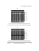
SI RAM
0 1 2 3Ð10 11Ð13 14 15
MCC LOOP SUPER MCSEL CNT BYT LST
SI RAM Address
1000x0
0x1
1 0 Regular Channel
1 0 0 0x1 0x1 1 0 Super Channel 1
1 0 0 0x2 0x1 1 0 Super Channel 2
1 0 0 0x2 0x1 1 0 Super Channel 2
1 0 0 0x2 0x1 1 0 Super Channel 2
1 0 0 0x3 0x1 1 0 Regular Channel
1 0 0 0x1 0x1 1 0 Super Channel 1
1 0 0 0x1 0x1 1 0 Super Channel 1
1000x4
0x1
1 1 Regular Channel
The super channel BD tables are associated with channels 1 and 2
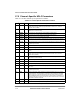
SI RAM