
Processor Users Manual

MOTOROLA Chapter 27. Multi-Channel Controllers (MCCs) 27-13
Part IV. Communications Processor Module
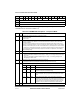
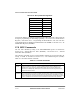
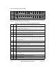
27.7.1 Channel Mode Register (CHAMR)ÑTransparent Mode
Figure 27-10 shows the user-initialized channel mode register, CHAMR, for transparent
mode.
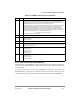
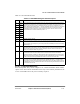
0x04 ZISTATE Word Zero-insertion machine state.(User-initialized to 0x10000207 for regular channel, and
0x30000207 for inverted channel)
0x08 ZIDATA0 Word Zero-insertion high word data buffer (User-initialized to 0xFFFFFFFF)
0x0C ZIDATA1 Word Zero-insertion low word data buffer (User-initialized to 0xFFFFFFFF)
0x10 TBDFlags Hword TxDB ßags, used by the CP (read-only for the user)
0x12 TBDCNT Hword Tx internal byte count. Number of remaining bytes in buffer, used by the CP (read-only
for the user)
0x14 TBDPTR Word Tx internal data pointer. Points to current absolute data address of channel, used by
the CP (read-only for the user)
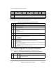
0x18 INTMSK Hword ChannelÕs interrupt mask ßag. See Section 27.6.2, ÒInterrupt Mask (INTMSK).Ó
0x1A CHAMR Hword Channel mode register. See Section 27.7.1, ÒChannel Mode Register (CHAMR)Ñ
Transparent Mode.Ó
0x1C Ñ Word Reserved
0x20 RSTATE Word Rx internal state. To start a receiver channel the user must write to RSTATE
0xHH80_0000. HH is the RSTATE high byte described in Section 27.6.4, ÒInternal
Receiver State (RSTATE).Ó
0x24 ZDSTATE Word Zero-deletion machine state (User-initialized to 0x00FFFFE0 for regular channel and
0x20FFFFE0 for inverted channel)
0x28 ZDDATA0 Word Zero-deletion high word data buffer (User-initialized to 0xFFFFFFFF)
0x2C ZDDATA1 Word Zero-deletion low word data buffer (User-initialized to 0xFFFFFFFF)
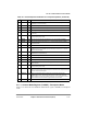
0x30 RBDFlags Hword RxBD ßags, used by the CP (read-only for the user)
0x32 RBDCNT Hword Rx internal byte count. Number of remaining bytes in buffer, used by the CP (read-
only for the user)
0x34 RBDPTR Word Rx internal data pointer. Points to current absolute data address of channel, used by
the CP (read-only for the user)
0x38 TMRBLR Hword Transparent maximum receive buffer length. DeÞnes the maximum number of bytes
written to a receiver buffer before moving to the next buffer for the respective channel.
This value must be 8 byte aligned.
0x3A RCVSYNC Hword Receive synchronization pattern. DeÞnes the synchronization pattern when
CHAMR[SYNC] is 0b1x. The two bytes are checked in reverse order (byte from
address 0x3B Þrst and byte from address 0x3A last). Non-inverted data is used for
synchronization even if the channel is programmed to invert the data.
0x3C Ñ Word Reserved
1
The offset is relative to dual-port RAM address 64*CH_NUM
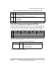
Table 27-7. Channel-Specific Parameters for Transparent Operation (Continued)
Offset
1
Name Width Description