
Processor Users Manual


MOTOROLA Chapter 28. Fast Communications Controllers (FCCs) 28-5
Part IV. Communications Processor Module
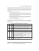
5 CDP CD pulse (transparent mode only)
0 Normal operation (envelope mode). CD
should envelope the frame; to negate CD while receiving
causes a CD
lost error.
1 Pulse mode. Once CD
is asserted (high to low transition), synchronization has been achieved,
and further transitions of CD
do not affect reception.
This bit must be set if this FCC is used in the TSA.
6 CTSP CTS
pulse
0 Normal operation (envelope mode). CTS
should envelope the frame; to negate CTS while
transmitting causes a CTS
lost error. See Section 28.11, ÒFCC Timing Control.Ó
1 Pulse mode. CTS
is asserted when synchronization is achieved; further transitions of CTS do not
affect transmission.
7 CDS CD
sampling
0 The CD
input is assumed to be asynchronous with the data. The FCC synchronizes it internally
before data is received. (This mode is illegal in transparent mode when SYNL = 0b00.)
1 The CD
input is assumed to be synchronous with the data, giving faster operation. In this mode,
CD
must transition while the receive clock is in the low state. When CD goes low, data is
received. This is useful when connecting MPC8260s in transparent mode since it allows the R
TS
signal of one MPC8260 to be connected directly to the CD
signal of another MPC8260.
8 CTSS CTS
sampling
0 The CTS
input is assumed to be asynchronous with the data. When it is internally synchronized
by the FCC, data is sent after a delay of no more than two serial clocks.
1 The CTS
input is assumed to be synchronous with the data, giving faster operation. In this mode,
CTS
must transition while the transmit clock is in the low state. As soon as CTS is low, data
transmission begins. This mode is useful when connecting MPC8260 in transparent mode
because it allows the R
TS signal of one MPC8260 to be connected directly to the CTS signal of
another MPC8260.
9--15 Ñ Reserved, should be 0.
16Ð17 SYNL Sync length (transparent mode only). Determines the operation of an FCC receiver conÞgured for
totally transparent operation only. See Section 32.3.1, ÒIn-Line Synchronization Pattern.Ó
00 The sync pattern in the FDSR is not used. An external sync signal is used instead (CD
signal
asserted: high to low transition).
01 Automatic sync (assumes always synchronized, ignores CD
signal).
10 8-bit sync. The receiver synchronizes on an 8-bit sync pattern stored in the FDSR. Negation of
CD
causes CD lost error.
11 16-bit sync. The receiver synchronizes on a 16-bit sync pattern stored in the FDSR. Negation of
CD
causes CD lost error.
18 RTSM RTS mode
0 Send idles between frames as deÞned by the protocol. R
TS is negated between frames (default).
1 Send ßags/syncs between frames according to the protocol. R
TS is asserted whenever the FCC
is enabled.
19Ð20 RENC Receiver decoding method. The user should set RENC = TENC in most applications.
00 NRZ
01 NRZI (one bit mode HDLC or transparent only)
1x Reserved
21 REVD Reverse data (valid for a totally transparent channel only)
0 Normal operation
1 The totally transparent channels on this FCC (either the receiver, transmitter, or both, as deÞned
by TTX and TRX) reverse bit order, transmitting the MSB of each octet Þrst.
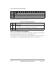
Table 28-1. GFMR Register Field Descriptions (Continued)
Field Name Description