
Processor Users Manual

29-26 MPC8260 PowerQUICC II UserÕs Manual MOTOROLA
Part IV. Communications Processor Module
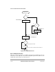
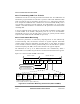
29.5.2.1 RM Cell Rate Representation
Rates in the RM cells are represented in a binary ßoating-point format using a 5-bit
exponent (e), a 9-bit mantissa (m), and a 1-bit nonzero ßag (nz), as shown in Figure 29-15.
Figure 29-15. Rate Format for RM Cells
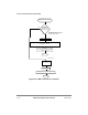
The rate (in cells/second) is calculated as in Figure 29-16.
Figure 29-16. Rate Formula for RM Cells
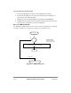
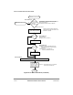
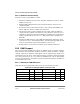
Initialize the trafÞc parameters (ER, MCR, PCR, or ICR) in the ABR protocol-speciÞc
connection tables using the rate formula in Figure 29-16.
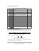
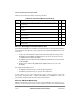
Table 29-7. Fields and their Positions in RM Cells
Fields Octet Bits Description Value
Header 1Ð5 All ATM cell header RM-VCC
PTI=6
ID 6 All Protocol ID 1
DIR 7 0 Direction of RM cell (0 = forward, 1 = backward)
BN 7 1 Backward notiÞcation (BN = 0, the cell was generated by the
source; BN=1, the cell was generated by the network or by the
destination)
CI 7 2 Congestion indication. (1 = congestion, 0 = otherwise)
NI 7 3 No increase indication. (1 = no increase allowed, 0 = otherwise)
RA 7 4 Not used (ATM Forum ABR) 0
Ñ 7 5-7 Reserved, should be cleared. 0
ER 8Ð9 All Explicit rate; see Section 29.5.2.1
CCR 10Ð11 All Current cell rate; see Section 29.5.2.1
MCR 12Ð13 All Min cell rate; see Section 29.5.2.1
QL 14Ð17 All Not used (ATM Forum ABR) 0
SN 18Ð21 All Not used (ATM Forum ABR) 0
Ñ 22Ð51 All Reserved, should be cleared. 0x6A for each byte
Ñ 52 0Ð5 Reserved, should be cleared. 0
CRC-10 52 6Ð7 CRC-10
53 All
0 1 2 3 4 5 6 7 8 9 10 11 12 13 14 15
0 nz Exponent Mantissa
Rate 2
e
1
m
512
---------+
èø
æö
´ nz´=