
Processor Users Manual

29-45 MPC8260 PowerQUICC II UserÕs Manual MOTOROLA
Part IV. Communications Processor Module
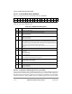
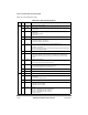
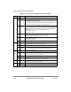
Table 29-16 describes RCT Þelds.
Table 29-16. RCT Field Descriptions
Offset Bits Name Description
0x00 0Ð1 Ñ Reserved, should be cleared.
2 GBL Global. Asserting GBL enables snooping of data buffers, BD, interrupt queues and
free buffer pool.
3Ð4 BO Byte orderingÑused for data buffers.
00 Reserved
01 PowerPC little endian
1x Big endian
5 Ñ Reserved, should be cleared.
6 DTB Data buffers bus
0 Data buffers reside on the 60x bus.
1 Data buffers reside on the local bus.
7 BIB BD, interrupt queues, free buffer pool and external SRTS logic bus
0 Reside on the 60x bus.
1 Reside on the local bus.
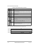
Note: When using AAL5, AAL1 in UDC mode, BDs and data should be placed on the
same bus (RCT[DTB]=RCT[BIB]).
8 Ñ Reserved, should be cleared.
9 BUFM Buffer mode. (AAL5 only) See Section 29.10.5.3, ÒATM Controller Buffers.Ó
0 Static buffer allocation mode. Each BD is associated with a dedicated buffer.
1 Global buffer allocation mode. Free buffers are fetched from global free buffer
pools.
10 SEGF OAM F5 segment Þltering
0 Do not send cells with PTI=100 to the raw cell queue.
1 Send cells with PTI=100 to the raw cell queue.
11 ENDF OAM F5 end-to-end Þltering
0 Do not send cells with PTI=101 to the raw cell queue.
1 Send cells with PTI=101 to the raw cell queue.
12Ð13 Ñ Reserved, should be cleared.
14Ð15 INTQ Points to one of four interrupt queues available.
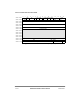
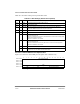
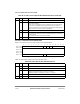
0x02 0 Ñ Internal use only. Initialize to 0.
1 INF (AAL5 only) Indicates the receiver state. Initialize to 0
0 In idle state.
1 In AAL5 frame reception state.
2Ð11 Ñ Internal use only. Initialize to 0.
12 ABRF (AAL5 only). Controls ABR ßow.
0 ABR ßow control is disabled.
1 ABR ßow control is enabled.
13Ð15 AAL AAL type
000 AAL0ÑReassembly with no adaptation layer
001 AAL1ÑATM adaptation layer 1 protocol
010 AAL5ÑATM adaptation layer 5 protocol
All others reserved.