
Processor Users Manual

29-46 MPC8260 PowerQUICC II UserÕs Manual MOTOROLA
Part IV. Communications Processor Module
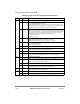
29.10.2.2.1 AAL5 Protocol-SpeciÞc RCT
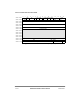
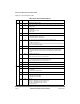
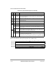
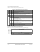
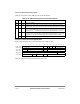
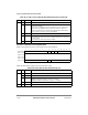
Figure 29-26 shows the AAL5 protocol-speciÞc area of an RCT entry.
0x04 Ñ RxDBPTR Receive data buffer pointer. Holds real address of current position in the Rx buffer.
0x08 Ñ Cell Time
Stamp
Used for reassembly time-out. Whenever a cell is received, the MPC8260 time stamp
timer is sampled and written to this Þeld. See Section 13.3.7, ÒRISC Time-Stamp
Control Register (RTSCR).Ó
0x0C Ñ RBD_Offset RxBD offset from RBD_BASE. Points to the channelÕs current BD. User-initialized to
0; updated by the CP.
0x0E-
0x18
Ñ Protocol-speciÞc area.
0x1A Ñ MRBLR Maximum receive buffer length. Used in both static and dynamic buffer allocation.
0x1C 0Ð1 Ñ Reserved, should be cleared.
2Ð7 PMT Performance monitoring table. Points to one of the available 64 performance
monitoring tables. The starting address of the table is PMT_BASE+PMT ´ 32. Can be
changed on-the-ßy.
8Ð15 RBD_BASE RxBD base. Points to the Þrst BD in the channelÕs RxBD table. The 8 most-signiÞcant
bits of the address are taken from BD_BASE_EXT in the parameter RAM. The four
least-signiÞcant bits of the address are taken as zeros.
0x1E 0Ð11
12Ð14 Ñ Reserved, should be cleared.
15 PM Performance monitoring. Can be changed on-the-ßy.
0 No performance monitoring for this VC.
1 Perform performance monitoring for this VC. Whenever a cell is received for this VC
the performance monitoring table that its code is written in the PMT Þeld is updated.
0 1 2 3 4 5 6 7 8 9 10 11 12 13 14 15
Offset + 0x0E TML
Offset + 0x10 RX CRC
Offset + 0x12
Offset + 0x14 RBDCNT
Offset + 0x16 Ñ
Offset + 0x18 Ñ RXBM RXFM Ñ BPOOL
Figure 29-26. AAL5 Protocol-Specific RCT
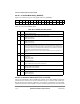
Table 29-16. RCT Field Descriptions (Continued)
Offset Bits Name Description