
Processor Users Manual

29-50 MPC8260 PowerQUICC II UserÕs Manual MOTOROLA
Part IV. Communications Processor Module
29.10.2.2.4 AAL0 Protocol-SpeciÞc RCT
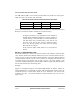
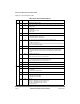
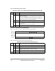
Figure 29-29 shows the layout for the AAL0 protocol-speciÞc RCT.
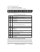
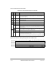
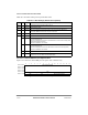
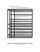
Table 29-20 describes AAL0 protocol speciÞc RCT Þelds.
0x18 0Ð3 Ñ Reserved, should be cleared.
4 SNEM Sequence number error ßag interrupt mask
0 This mode is disabled.
1 When an out-of-sequence error occurs, an RXB interrupt is sent to the interrupt
queue even if RCT[RXBM] is cleared. Note that this mode is the buffer error
reporting mechanism during automatic data forwarding (ATM-to-TDM bridging)
when no buffer processing is required (RCT[RXBM]=0).
5Ð7 Ñ Reserved, should be cleared.
8 RXBM Receive buffer interrupt mask
0 The receive buffer event of this channel is disabled. (The event is not sent to the
interrupt queue.)
1 The receive buffer event of this channel is enabled.
9Ð15 Ñ Reserved, should be cleared.
0 1 2 3 4 5 6 7 8 9 10 11 12 13 14 15
Offset + 0x0E Ñ 0 1 INVE Ñ
Offset + 0x10 Ñ
Offset + 0x12
Offset + 0x14
Offset + 0x16
Offset + 0x18 Ñ RXBM Ñ
Figure 29-29. AAL0 Protocol-Specific RCT
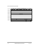
Table 29-20. AAL0-Specific RCT Field Descriptions
Offset Bits Name Description
0x0E 0-7 Ñ Reserved, should be cleared.
8-9 0b01 Must be programmed to 0b01 for AAL0.
10 INVE Inverted empty.
0 RxBD[E] is interpreted normally (1 = empty, 0 = not empty).
1 RxBD[E] is handled in negative logic (0 = empty, 1 = not empty).
11-15 Ñ Reserved, should be cleared.
0x10 Ñ Ñ Reserved, should be cleared.
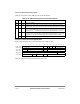
Table 29-19. AAL1 Protocol-Specific RCT Field Descriptions (Continued)
Offset Bits Name Description