
Processor Users Manual

29-61 MPC8260 PowerQUICC II UserÕs Manual MOTOROLA
Part IV. Communications Processor Module
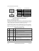
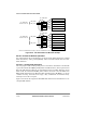
29.10.4 APC Data Structure
The APC data structure consists of three elements: the APC parameter tables for the PHY
devices, the APC priority table, and the APC scheduling tables. See Figure 29-38.
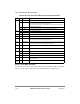
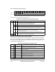
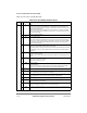
Table 29-28. OAMÑPerformance Monitoring Table Field Descriptions
Offset Bits Name Description
0x00 0 FMCE Enables FMC transmission. Initialize to 1.
1 TSTE FMC time stamp enable
0 The time stamp Þeld of the FMC is coded with all 1Õs.
1 The value of the time stamp timer is inserted into the time stamp Þeld of the FMC.
2Ð4 Ñ Reserved, should be cleared.
5Ð15 TCC TX cell count. Used by the CP to count data cells sent. Initialize to zero.
0x02 0Ð4 Ñ Reserved, should be cleared.
5Ð15 BLCKSIZE Performance monitoring block size ranging from 1 to 2,047 cells.
0x04 Ñ TUC1 Total user cell 1. Count of CLP = 1 user cells (modulo 65,536) sent. Initialize to 0.
0x06 Ñ TUC0 Total user cell 0. Count of CLP = 0 user cells (modulo 65,536) sent. Initialize to 0.
0x08 Ñ BEDC0+1-Tx Block error detection code 0+1Ðtransmitted cells. Even parity over the payload of the
block of user cells sent since the last FMC. Initialize to 0.
0x0A Ñ BEDC0+1-RX Block error detection code 0+1Ðreceived cells. Even parity over the payload of the
block of user cells received since the last FMC. Initialize to 0.
0x0C Ñ TRCC1 Total received cell 1. Count of CLP = 1 user cells (modulo 65,536) received. Initialize
to 0.
0x0E Ñ TRCC0 Total received cell 0. Count of CLP = 0 user cells (modulo 65,536) received. Initialize
to 0.
0x10 0Ð7 Ñ Reserved, should be cleared.
8Ð15 SN-FMC Sequence number of the last FMC sent. Initialize to 0.
0x12 Ñ Ñ Reserved, should be cleared.
0x14 Ñ PMCH PM cell header. Holds the ATM cell header of the FMC, BRC to be inserted by the CP
into the Tx cell ßow.
0x18Ð
0x1E
Ñ Ñ Reserved, should be cleared.