
Processor Users Manual

29-62 MPC8260 PowerQUICC II UserÕs Manual MOTOROLA
Part IV. Communications Processor Module
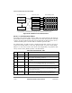
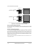
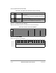
Figure 29-38. ATM Pace Control Data Structure
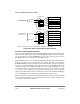
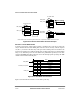
29.10.4.1 APC Parameter Tables
Each PHYÕs APC parameter table, shown in Table 29-29, holds parameters that deÞne the
priority table location, the number of priority levels, and other APC parameters. The table
resides in the dual-port RAM. The parameter APCP_BASE, described in Section 29.10.1,
ÒParameter RAM,Ó points to the base address of PHY#0Õs parameter table.
For multiple PHYs, the table structure is duplicated. Each table resides in 32 bytes of
memory. The starting address of each APC parameter table is given by APCP_BASE +
PHY# ´ 32. Note however that in slave mode with multiple PHYs, the parameter table
always resides at APCP_BASE regardless of the PHY address.
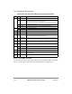
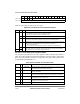
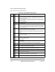
Table 29-29. APC Parameter Table
Offset
1
Name Width Description
0x00 APCL_FIRST Hword Address of Þrst entry in the priority table. Must be 8-byte aligned. User-initialized.
0x02 APCL_LAST Hword Address of last entry in the priority table. Must be 8-byte aligned. User-initialized
as APCL_FIRST + 8 x (number_of_priorities - 1).
0x04 APCL_PTR Hword Address of current priority entry used by the CP. User-initialized with
APCL_FIRST.
0x06 CPS Byte Cells per slot. Determines the number of cells sent per APC slot. See
Section 29.3.2, ÒAPC Unit Scheduling Mechanism.Ó User-deÞned. (0x01 = 1 cell;
0xFF = 255 cells.) Note that if ABR is used, CPS must be a power of two.
0x07 CPS_CNT Byte Cells sent per APC slot counter. User-initialized to CPS; used by the CP.
0x08 MAX_ITERATIO
N
Byte Max iteration allowed. Number of scan iterations allowed in the APC. User-
deÞned. This parameter limits the time spent in a single APC routine, thereby
avoiding excessive APC latency.
0x09 CPS_ABR Byte ABR only. Cells per slot represented as a power of two. User-deÞned. (For
example, if CPS is 1, CPS_ABR = 0x00; if CPS is 8, CPS_ABR = 0x03.)
Priority 1
APC Priority Table
APC Parameter Tables
Parameter Table
PHY #0
Parameter Table
PHY #1
Parameter Table
PHY #31
Priority 2
Priority 3
Priority 4
Priority 5
Priority 6
Priority 7
Priority 8
APC Scheduling Tables
Priority 1 Scheduling Table
Priority 2 Scheduling Table
Priority 3 Scheduling Table
Priority 4 Scheduling Table
Priority 5 Scheduling Table
Priority 6 Scheduling Table
Priority 7 Scheduling Table
Priority 8 Scheduling Table
Note: The shaded areas represent the active structures for an example implementation of PHY #0
with two priorities. (The unshaded areas and dashed arrows represent unused structures.)