
Processor Users Manual

31-4 MPC8260 PowerQUICC II UserÕs Manual MOTOROLA
Part IV. Communications Processor Module
31.4 HDLC Parameter RAM
When an FCC operates in HDLC mode, the protocol-speciÞc area of the FCC parameter
RAM is mapped with the HDLC-speciÞc parameters in Table 31-1.
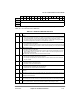
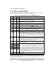
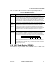
Table 31-1. FCC HDLC-Specific Parameter RAM Memory Map
Offset
1
1
Offset from FCC base: 0x8400 (FCC1), 0x8500 (FCC2) and 0x8600 (FCC3); see Section 13.5.2, ÒParameter RAM.Ó
Name Width Description
0x38 Ñ 3 Words Reserved
0x44 C_MASK Word CRC constant. For the 16-bit CRC-CCITT, initialize C_MASK to 0x0000_F0B8. For the
32-bit CRC-CCITT, initialize C_MASK to 0xDEBB_20E3.
0x48 C_PRES Word CRC preset. For the 16-bit CRC-CCITT, initialize C_PRES to 0x0000_FFFF. For the
32-bit CRC-CCITT, initialize C_PRES to 0xFFFF_FFFF.
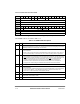
0x4C DISFC
2
2
DISFC, CRCEC, ABTSC, and NMARCÑThese 16-bit (modulo 216) counters are maintained by the CP. The user can
initialize them while the channel is disabled.
Hword Discard frame counter. Counts error-free frames discarded due to lack of buffers.
0x4E CRCEC
2
Hword CRC error counter. Counts frames not addressed to the user or frames received in the
BSY condition, but does not include overrun, CD
lost, or abort errors.
0x50 ABTSC
2
Hword Abort sequence counter
0x52 NMARC
2
Hword Nonmatching address Rx counter. Counts nonmatching addresses received (error-free
frames only). See the HMASK and HADDR[1Ð4] parameter description.
0x54 MAX_CNT Word Max_length counter. Temporary decrementing counter that tracks frame length.
0x58 MFLR Hword Max frame length register. If the HDLC controller detects an incoming HDLC frame that
exceeds the user-deÞned value in MFLR, the rest of the frame is discarded and the LG
(Rx frame too long) bit is set in the last BD belonging to that frame. The HDLC controller
waits for the end of the frame and then reports the frame status and length in the last
RxBD. MFLR includes all in-frame bytes between the opening and closing ßags (address,
control, data, and CRC).
0x5A RFTHR Hword Received frames threshold. Used to reduce the interrupt overhead that might otherwise
occur when a series of short HDLC frames arrives, each causing an RXF interrupt. By
programming RFTHR, the user lowers the frequency of RXF interrupts, which occur only
when the RFTHR value is reached. Note that the user should provide enough empty
RxBDs to receive the number of frames speciÞed in RFTHR.
0x5C RFCNT Hword Received frames count. A decrementing counter used to implement this feature. Initialize
this counter with RFTHR.
0x5E HMASK Hword HMASK and HADDR[1Ð4]. The HDLC controller reads the frame address from the HDLC
receiver, checks it against the four address register values, and masks the result with
HMASK. In HMASK, a 1 represents a bit position for which address comparison should
occur; 0 represents a masked bit position. When addresses match, the address and
subsequent data are written into the buffers. When addresses do not match and the
frame is error-free, the nonmatching address received counter (NMARC) is incremented.
Note that for 8-bit addresses, mask out (clear) the eight high-order bits in HMASK. The
eight low-order bits and HADDRx should contain the address byte that immediately
follows the opening ßag. For example, to recognize a frame that begins 0x7E (ßag), 0x68,
0xAA, using 16-bit address recognition, HADDRx should contain 0xAA68 and HMASK
should contain 0xFFFF. See Figure 31-2.
0x60 HADDR1 Hword
0x62 HADDR2 Hword
0x64 HADDR3 Hword
0x66 HADDR4 Hword
0x68 TS_TMP Hword Temporary storage
0x6A TMP_MB Hword Temporary storage