
Processor Users Manual


31-16 MPC8260 PowerQUICC II UserÕs Manual MOTOROLA
Part IV. Communications Processor Module
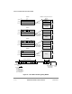
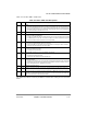
Figure 31-8. HDLC Interrupt Event Example
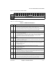
31.10 FCC Status Register (FCCS)
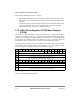
The FCCS register, shown in Figure 31-9, allows the user to monitor real-time status
conditions on the RXD line. The real-time status of the CTS
and CD signals are part of the
parallel I/O port; see Chapter 35, ÒParallel I/O Ports.Ó
Bits 0 1 2 3 4 5 6 7
Field Ñ FG Ñ ID
Reset 0000_0000
R/W R
Addr 0x11318 (FCCS1), 0x11338 (FCCS2), 0x11358 (FCCS3)
Figure 31-9. FCC Status Register (FCCS)
CD IDL FLG RXB RXF IDL CD
Line Idle
Stored in Rx Buffer
RXD
CD
Frame
Received by HDLC
Time
Line Idle
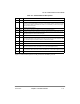
TXD
R
TS
Frame
Transmitted by HDLC
CTS
TXB CTCT
Line Idle Line Idle
Stored in Tx Buffer
Notes:
HDLC FCCE
Events
1. RXB event assumes receive buffers are 6 bytes each.
2. The second IDL event occurs after 15 ones are received in a row.
3. The FLG interrupts show the beginning and end of flag reception.
4. The FLG interrupt at the end of the frame may precede the RXF interrupt due to receive FIFO latency.
5. The CD event must be programmed in the parallel I/O port, not in the FCC itself.
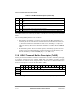
Notes:
HDLC FCCE
Events
1. TXB event shown assumes all three bytes were put into a single buffer.
2. Example shows one additional opening flag. This is programmable.
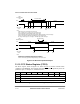
FF A A C I I I CR CR F
FLG FLG
FLG
6. F = flag, A = address byte, C = control byte, I = information byte, and CR = CRC byte
FFAACCRCRF
3. The CT event must be programmed in the parallel I/O port, not in the FCC itself.