
Processor Users Manual


34-8 MPC8260 PowerQUICC II UserÕs Manual MOTOROLA
Part IV. Communications Processor Module
Table 34-3 describes I2BRG Þelds.
34.4.4 I
2
C Event/Mask Registers (I2CER/I2CMR)
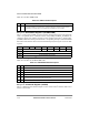
The I
2
C event register (I2CER) is used to generate interrupts and report events. When an
event is recognized, the I
2
C controller sets the corresponding I2CER bit. I2CER bits are
cleared by writing ones; writing zeros has no effect. Setting a bit in the I
2
C mask register
(I2CMR) enables and clearing a bit masks the corresponding interrupt. Unmasked I2CER
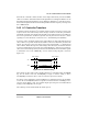
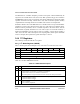
bits must be cleared before the CP clears internal interrupt requests. Figure 34-9 shows both
registers.
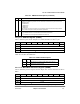
Table 34-4 describes the I2CER/I2CMR Þelds.
34.4.5 I
2
C Command Register (I2COM)
The I
2
C command register, shown in Figure 34-10, is used to start I
2
C transfers and to select
master or slave mode.
Table 34-3. I2BRG Field Descriptions
Bits Name Description
0Ð7 DIV Division ratio 0Ð7. SpeciÞes the divide ratio of the BRG divider in the I
2
C clock generator. The output of
the prescaler is divided by 2 * ([DIV0ÐDIV7] + 3) and the clock has a 50% duty cycle. DIV must be
programmed to a minimum value of 3 if the digital Þlter is disabled and 6 if it is enabled.
Bit 0 1 2 3 4 5 6 7
Field Ñ TXE Ñ BSY TXB RXB
Reset 0000_0000
R/W R/W
Addr 0x11870(I2CER)/0x11874 I2CMR)
Figure 34-9. I
2
C Event/Mask Registers (I2CER/I2CMR)
Table 34-4. I2CER/I2CMR Field Descriptions
Bits Name Description
0Ð2 Ñ Reserved and should be cleared.
3 TXE Tx error. Set when an error occurs during transmission.
4 Ñ Reserved and should be cleared.
5 BSY Busy. Set after the Þrst character is received but discarded because no Rx buffer is available.
6 TXB Tx buffer. Set when the Tx data of the last character in the buffer is written to the Tx FIFO. Two character
times must elapse to guarantee that all data has been sent.
7 RXB Rx buffer. Set after the last character is written to the Rx buffer and the RxBD is closed.