
Processor Users Manual

35-8 MPC8260 PowerQUICC II UserÕs Manual MOTOROLA
Part IV. Communications Processor Module
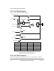
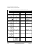
Figure 35-7. Primary and Secondary Option Programming
In the tables below, the default value for a primary option is simply a reference to the
secondary option. In the secondary option, the programming is relevant only if the primary
option is not used for the function.
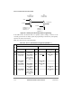
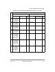
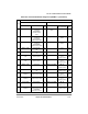
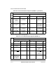
Table 35-5 shows the port A pin assignments.
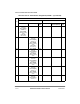
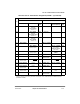
Table 35-5. Port AÑDedicated Pin Assignment (PPARA = 1)
Pin
Pin Function
PSORA = 0 PSORA = 1
PDIRA = 1 (Output) PDIRA = 0 (Input)
Default
Input
PDIRA = 1 (Output)
PDIRA = 0 (Input, or
Inout if SpeciÞed)
Default
Input
PA31
FCC1: TxEnb
UTOPIA master
FCC1: TxEnb
UTOPIA slave
GND FCC1: COL
MII
GND
PA30
FCC1: TxClav
UTOPIA slave
FCC1: TxClav
UTOPIA master
FCC1: TxClav0
MPHY, master, direct
polling
GND FCC1: RTS FCC1: CRS
MII
GND
PA29 FCC1: TxSOC
UTOPIA
FCC1: TX_ER
MII
PA28 FCC1: RxEnb
UTOPIA master
FCC1: RxEnb
UTOPIA slave
GND FCC1: TX_EN
MII
PA27 FCC1: RxSOC
UTOPIA
GND FCC1: RX_DV
MII
GND
PA26
FCC1: RxClav
UTOPIA slave
FCC1: RxClav
UTOPIA master
FCC1: RxClav0
MPHY, master, direct
polling
GND FCC1: RX_ER
MII
GND
MUX
MUX
Pin PA8
Pin PD4
GND
PPARA[8] == 1 &
PPARD[4] == 1 &
PSORA[8] == 0 &
PDIRA[8] == 0
PSORD[4] == 1 &
PDIRD[4] == 0
Primary option
Secondary option
PD4 PA8
0
1
0
1
for SMC2 RxD
for SMC2 RxD
to SMC2 RxD