
Instruction Manual


5 - 2 TEST SETUP & TESTING
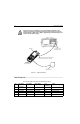
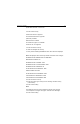
Connect the red (+) and black (-) wires of the battery eliminator to the
respective positive and negative points of the power supply, and use the
correct voltage (7.4VDC, max. 7.8VDC). Neglecting this would damage your
radio and/or the power supply.
Figure 17 Typical Test Setup
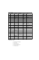
Test Check List
The following table summarises the required test setups.
No. Test Name Test Setup Radio Setup Test
Conditions
Limits
1. Base Station
Registration
380-430MHz Control Channel 390.125 MHz 3605 TETRA 380+0MS
380-430MHz Traffic Channel 390.125 MHz 3605 TETRA 380+0MS
Time Slot 3
Country Code 234
IFR 3902 / IFR 2968
N-TYPE
RF CONNECTOR
with adapter to SM
A
7.4 V
POWER SUPPLY
ANTENNA RF ADAPTER (P/N: 66007029001)
with RF cable (SMA connector, male type)
MTP810 Ex
BATTERY
ELIMINATOR
(P/N: 66007029002)