
Computer Hardware User Manual


MVME3100 Installation and Use (V3100A/IH1)
Chapter 1 Hardware Preparation and Installation
8
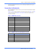
Note The RTM EEPROM address switches must be set for address $AA in order for this device
to be accessible by MotLoad.
Hardware Installation
Installing the MVME3100 into a Chassis
Use the following steps to install the MVME3100 into your computer chassis.
1. Attach an ESD strap to your wrist. Attach the other end of the ESD strap to an electrical ground
(refer to Unpacking Guidelines). The ESD strap must be secured to your wrist and to ground
throughout the procedure.
2. Remove any filler panel that might fill that slot.
3. Install the top and bottom edge of the MVME3100 into the guides of the chassis.
!
Warning
Warnin g
Only use injector handles for board insertion to avoid damage/deformation to the front
panel and/or PCB. Deformation of the front panel can cause an electrical short or other
board malfunction.
4. Ensure that the levers of the two injector/ejectors are in the outward position.
5. Slide the MVME3100 into the chassis until resistance is felt.
6. Simultaneously move the injector/ejector levers in an inward direction.
7. Verify that the MVME3100 is properly seated and secure it to the chassis using the two screws
located adjacent to the injector/ejector levers.
8. Connect the appropriate cables to the MVME3100.
Table 1-6. EEPROM Address Settings
Device Address A(2:0) SW1 SW2 SW3
$A0 000 ON ON ON
$A2 001 OFF ON ON
$A4 010 ON OFF ON
$A6 011 OFF OFF ON
$A8 100 ON ON OFF
$AA (Factory) 101 OFF ON OFF
$AC 110 ON OFF OFF
$AE 111 OFF OFF OFF